
Two-degree-of-freedom piezoelectric driving nanometer positioning platform

A nano-positioning and piezoelectric drive technology, applied in the direction of machines/supports, supporting machines, mechanical equipment, etc., can solve the problems of small load bearing capacity, difficult to reach the stroke, low driving power, etc., to prevent breakdown and reduce The effect of motion cross-coupling and high space utilization

Active Publication Date: 2015-05-06
三英精控(天津)科技有限公司
View PDF8 Cites 41 Cited by
  • Summary
  • Abstract
  • Description
  • Claims
  • Application Information

AI Technical Summary

Problems solved by technology

Compared with the traditional driving method, the piezoelectric ceramic driver has the advantages of high control precision, fast response, large driving force, low driving power and wide operating frequency, but it is difficult to achieve a large stroke
The amplification mechanisms used in nanopositioning platforms usually include traditional lever amplification and bridge amplification mechanisms. Lever amplification has high rigidity, and the spatial configuration must be increased in order to achieve a larger magnification; bridge amplification has a larger amplification ratio, but Small stiffness, too small load carrying capacity
The existing design platform cannot achieve a good compromise between large stiffness and large stroke, large amplification ratio and small overall configuration, high precision and easy decoupling. Based on the shortcomings of existing technologies, a new type of The nano-shift positioning system with high precision, large stroke, high stiffness and good decoupling of the mechanism form and control method has important theoretical significance and engineering practical value

Method used


Image

  • Two-degree-of-freedom piezoelectric driving nanometer positioning platform
  • Two-degree-of-freedom piezoelectric driving nanometer positioning platform
  • Two-degree-of-freedom piezoelectric driving nanometer positioning platform

Examples


Embodiment Construction

[0040] Below in conjunction with accompanying drawing and embodiment the present invention will be further described:

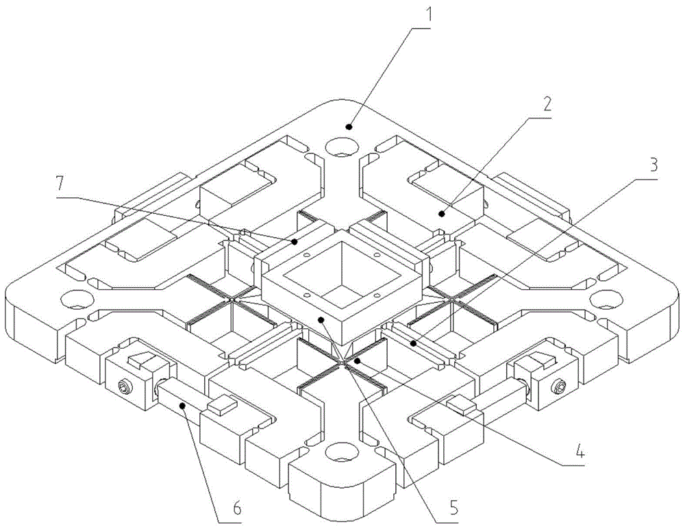
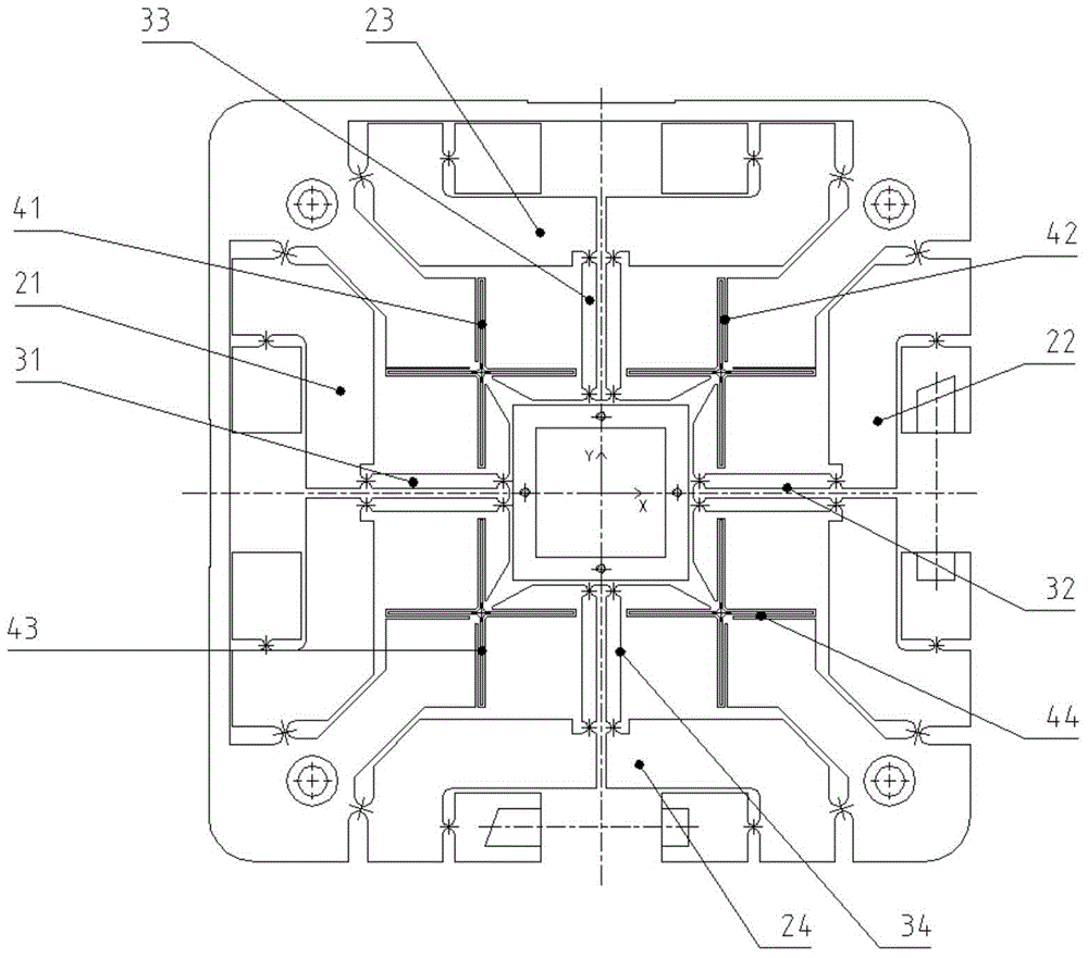
[0041] like figure 1 and figure 2 As shown, the present invention is a micro-movement nano-shift positioning platform driven by a piezoelectric ceramic driver and decoupled in parallel in the XY direction, including a base 1, an L-shaped symmetrical amplifying lever 2, and a composite parallel four-bar guide mechanism 3 , Cross-shaped XY decoupling mechanism 4, XY motion platform body 5, piezoelectric ceramic driver 6, laser ruler plane mirror and mirror frame 7.

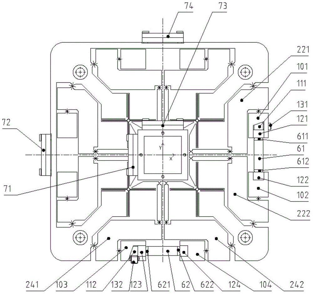
[0042] The XY motion platform body 5 and the base 1 pass through the fully compliant mechanism in the X-axis direction, the fully compliant mechanism in the Y-axis direction, the first cross-shaped XY decoupling mechanism 41 with four-corner symmetry, and the second cross-shaped XY decoupling mechanism 42 , the third cross-shaped XY decoupling mechanism 43 and the fourth cross-shaped XY decoupli...


PUM


Abstract

The invention discloses a two-degree-of-freedom piezoelectric driving nanometer positioning platform. The two-degree-of-freedom piezoelectric driving nanometer positioning platform is characterized in that an XY motion platform body is connected with a base through an X-axis full compliant mechanism, a Y-axis full compliant mechanism and a cross-shaped XY decoupling mechanism; laser ruler planar mirrors for checking X-direction motion and Y-direction motion are arranged on the side faces of the XY motion platform body and the base respectively; the laser ruler planar mirrors are matched with laser ruler reading heads for detecting X and Y directions respectively to finish the detection and feedback of two-degree-of-freedom motion of the nanometer positioning platform together; piezoelectric ceramic drivers are embedded into the X-axis full compliant mechanism and the Y-axis full compliant mechanism respectively. The two-degree-of-freedom piezoelectric driving nanometer positioning platform has the beneficial effects that flexible hinges are taken as a kinematic pair, and motion is transmitted and decoupled through micro-deformation, so that clearance errors introduced in an assembly process are reduced, and the accuracy of motion transmission is increased.

Description

technical field [0001] The invention relates to a nanometer precision positioning workbench, in particular, it can be applied to nanolithography, scanning imaging, preparation of quantum functional materials, biomedical engineering, micro-electromechanical systems and other high-precision positioning occasions, and can provide precise plane positioning and tracking Two-degree-of-freedom parallel nanopositioning stage. Background technique [0002] In recent years, high-tech technologies such as microelectronic devices and integrated chip processing technology, scanning microscopic imaging technology, quantum material preparation technology, and biomedical engineering technology have developed vigorously, and the precision and performance that their systems can achieve are to a large extent Rely on the precision and performance of its nanoshift positioning subsystem. In order to improve the overall accuracy and processing efficiency of the system, and expand its functions, i...

Claims


Application Information

Patent Timeline
IPC IPC(8): F16M11/04F16M11/18
Inventor 闫鹏孙玉琼
Owner 三英精控(天津)科技有限公司
Learn More