
A limit device for rolling cage machine

A technology of limiting device and rolling cage, applied in auxiliary devices, metal processing equipment, auxiliary welding equipment, etc., can solve the problems of affecting the construction period, affecting the progress, and low construction efficiency, so as to ensure the welding accuracy, reduce the gap error, artificial low cost effect

Active Publication Date: 2020-03-03
HENAN HIGHWAY ENG GROUP +1
View PDF4 Cites 0 Cited by
  • Summary
  • Abstract
  • Description
  • Claims
  • Application Information

AI Technical Summary

Problems solved by technology

[0002] At present, in pile foundation construction, manual processing of steel cages is generally used, which is relatively low in construction efficiency and difficult to control the processing quality of steel cages. In order to ensure the processing quality and improve the processing efficiency of steel cages, some projects have gradually begun to use rolling cage machines. Steel cage
In the actual welding of the rolling cage machine, the end of the main reinforcement in the steel cage is at the required end face position. This visual inspection method has the disadvantage that all the steel bars of the steel cage after production cannot be guaranteed to be in the required position, resulting in the subsequent splicing of the steel cage. The gap error is very large, and it needs to be pre-assembled on site, most of which need to be reworked and aligned, and the splicing on the construction site is extremely difficult and takes a long time, which restricts on-site construction and reduces construction efficiency
Therefore, manually aligning the ends of steel bars has low production quality, high rework rate, and low production efficiency, which often affects the progress of the next process, affects the construction period, consumes time and effort, and increases labor costs.

Method used


Image

  • A limit device for rolling cage machine
  • A limit device for rolling cage machine
  • A limit device for rolling cage machine

Examples


Embodiment Construction

[0019] The following will clearly and completely describe the technical solutions in the embodiments of the present invention with reference to the accompanying drawings in the embodiments of the present invention. Obviously, the described embodiments are only some, not all, embodiments of the present invention. Based on the embodiments of the present invention, all other embodiments obtained by persons of ordinary skill in the art without making creative efforts belong to the protection scope of the present invention.

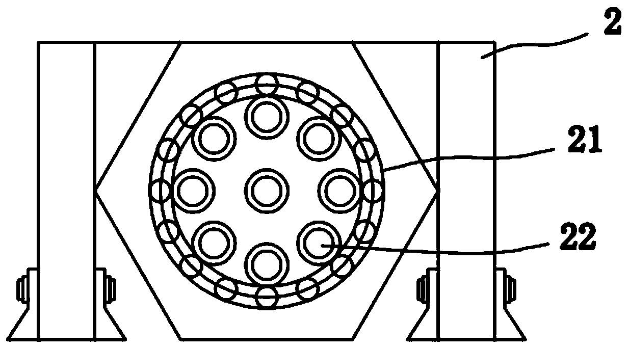
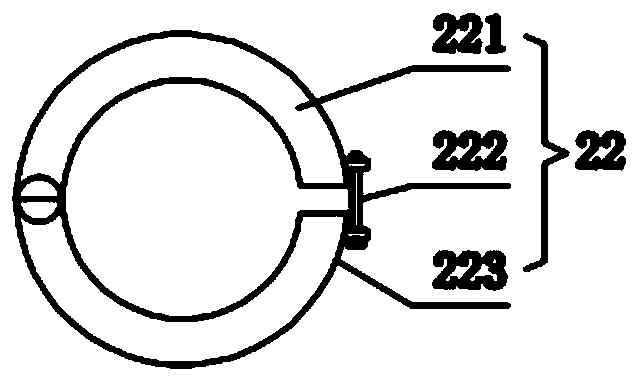
[0020] see Figure 1-6 , the present invention provides a technical solution: a limiting device for a rolling cage machine, including a mounting base 1, a rotating support device 2 is fixedly installed on the top left end of the mounting base 1, and the rotating supporting device 2 The left side rotating shaft 3 is connected with the drive motor 4 through a belt, and the drive motor 4 is fixed on the installation base 1, and the right end of the installation b...


PUM


Abstract

The invention discloses a limit device for a rolling cage machine in the technical field of tooling equipment, which includes a mounting base, a rotating supporting device is fixedly installed on the left end of the top of the mounting base, and a rotating shaft on the left side of the rotating supporting device The drive motor is connected to the drive motor through a belt, and the drive motor is fixed on the installation base. The right end of the installation base is slidingly connected to the limit device, and the control device is fixedly installed on the side wall of the limit device. The rotating support device There is also a reinforcement cage supporting assembly installed between the limit device and the present invention, by installing a displacement sensor in the limit ring, when the two groups of steel bars are in the docking process, by reading the data on the displacement sensor, thereby minimizing the two The gap error that occurs during the butt joint process of the steel cages ensures the welding accuracy of the steel cages, which has high production efficiency, low labor costs, and high production efficiency of the steel cages.

Description

technical field [0001] The invention discloses a limit device for a rolling cage machine, and specifically belongs to the technical field of tooling equipment. Background technique [0002] At present, in pile foundation construction, manual processing of steel cages is generally used, which is relatively low in construction efficiency and difficult to control the processing quality of steel cages. In order to ensure the processing quality and improve the processing efficiency of steel cages, some projects have gradually begun to use rolling cage machines. Steel cage. In the actual welding of the rolling cage machine, the end of the main reinforcement in the steel cage is at the required end face position. This visual inspection method has the disadvantage that all the steel bars of the steel cage after production cannot be guaranteed to be in the required position, resulting in the subsequent splicing of the steel cage. The gap error is very large, and it needs to be pre-a...

Claims


Application Information

Patent Timeline
Patent Type & Authority Patents(China)
IPC IPC(8): B23K37/04B23K37/047
CPCB23K37/0426B23K37/047
Inventor 黄春水王方涛高涛钱春花张占锋邓维辉巴启浩宋群生邓振江郑磊磊李本波王德敏陈丽芳张森闫晓华
Owner HENAN HIGHWAY ENG GROUP
Learn More