Method for generating biogas by using U-shaped multi-region mixed stirring type super-efficient generating system

A mixing and generating system technology, applied in the field of biogas fermentation system, can solve the problems of short fermentation efficiency route, poor convection effect of biogas slurry, uneven distribution of bacteria, etc., to reduce the difficulty of operation, reduce difficulty, facilitate feeding and The effect of discharge

Inactive Publication Date: 2015-05-06
李俊
View PDF0 Cites 0 Cited by
  • Summary
  • Abstract
  • Description
  • Claims
  • Application Information

AI Technical Summary

Problems solved by technology

[0004] In order to solve the deficiencies of the prior art, the technical problem to be solved by the present invention is that the fermentation efficiency route of the traditional biogas digester is short, the fermentation efficiency is low, and the biogas slurry convection effect is poor, resulting in uneven distribution of bacteria, etc.

Method used


Image

  • Method for generating biogas by using U-shaped multi-region mixed stirring type super-efficient generating system
  • Method for generating biogas by using U-shaped multi-region mixed stirring type super-efficient generating system
  • Method for generating biogas by using U-shaped multi-region mixed stirring type super-efficient generating system

Examples


Embodiment Construction

[0034] The technical solutions in the embodiments of the present invention will be clearly and completely described below in conjunction with the accompanying drawings in the embodiments of the present invention. Obviously, the described embodiments are only some, not all, embodiments of the present invention. Based on the embodiments of the present invention, all other embodiments obtained by persons of ordinary skill in the art without making creative efforts belong to the protection scope of the present invention.

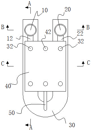
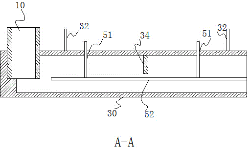
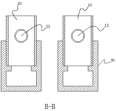
[0035] Such as figure 1 As shown, the horseshoe-shaped multi-area mixed flow stirring ultra-efficient biogas generation system is mainly composed of a feed pipe 10, a discharge pipe 20, a fermentation pipe 30, and a water pressure room 40. The fermentation pipe 30 is a U-shaped fermentation pipe. The cross-sectional shape of the fermentation pipeline can be a geometric shape such as a prototype, a rectangle, and an ellipse. The U-shaped fermentation pipeline 30 ...


PUM


Abstract

The invention discloses a method for generating biogas by using a U-shaped multi-region mixed stirring type super-efficient generating system. The method comprises the following steps: pouring a fermentation raw material into a U-shaped fermentation pipeline by virtue of a feed pipe, and fermenting in the U-shaped fermentation pipeline to generate biogas; collecting the biogas in a fermentation region formed between the side walls of feed / discharge pipes and adjacent gas baffle plates or between the adjacent gas baffle plates, wherein the biogas occupies the space in the fermentation region and extrudes biogas slurry in the fermentation region to perform convection, and the biogas slurry discharged from the fermentation pipeline flows to the feed pipe, the discharge pipe and a bacterium distribution device, and flows into a water pressure room by virtue of a drain pipe of the feed pipe, a drain pipe of the discharge pipe and a drain pipe of the bacterium distribution device; and the biogas stored in any fermentation region is used to ensure that the gas pressure of the biogas in the fermentation region is reduced, the biogas slurry in adjacent fermentation regions flows into the fermentation region in which the biogas is used, and the biogas slurry stored in the water pressure room flows back into the fermentation pipe by virtue of the drain pipes of the feed pipe, the discharge pipe and the bacterium distribution device, thereby finishing the circular flow of the biogas slurry.

Description

technical field [0001] The invention relates to an anaerobic fermentation device, in particular to a biogas fermentation system. Background technique [0002] The working principle of the traditional biogas digester is that when biogas is generated in the pond, the biogas in the gas storage room increases continuously, and the pressure continues to increase, forcing the liquid level in the main pool to drop, and a part of the material liquid is squeezed out into the hydraulic room. When people turn on the stove, the pressure in the biogas digester gradually drops, and the feed liquid in the hydraulic chamber continuously flows back to the main pond. In this way, gas is produced and used continuously, so that the pressure in the fermentation room and the discharge room is always maintained in a state of pressure balance. [0003] Traditional biogas digesters have short fermentation routes, poor fluidity of biogas slurry, and uneven distribution of bacteria, resulting in a dec...

Claims


Application Information

Patent Timeline
Patent Type & Authority Applications(China)
IPC IPC(8): C12M1/107C12P5/02C02F11/04
CPCC12M21/04C12M23/06C12M23/34C12P5/023Y02E50/30
Inventor 李俊
Owner 李俊
Why Eureka
Try Eureka