A nanofiber foam-based oil and gas capture device and its preparation method
A nanofiber, oil and gas technology, applied in chemical instruments and methods, other chemical processes, alkali metal oxides/hydroxides, etc., to improve the efficiency of oil and gas adsorption and recovery, ensure effective recycling, and efficient oil and gas capture.
- Summary
- Abstract
- Description
- Claims
- Application Information
AI Technical Summary
Problems solved by technology
Method used
Image
Examples
Embodiment 1
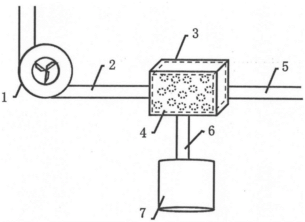
[0028] Such as figure 1As shown, it is a schematic structural diagram of a nanofiber foam-based oil and gas capture device. The nanofiber foam-based oil and gas capture device includes a gas collection pump 1 connected to a gas delivery pipe 2, and the gas delivery pipe 2 is connected to an oil and gas capture component, and the oil and gas capture component is connected to The exhaust pipe 5 and the collecting pipe 6, the collecting pipe 6 is connected to the oil substance recovery tank 7, wherein the oil and gas collection assembly includes a protective box 3, and the nanofiber-based foam material 4 is arranged in the protective box 3. The nanofiber-based foam material 4 is obtained by super-oleophilic and hydrophobic modification of the nanofiber foam material by high-voltage electrostatic spraying method. The high-voltage electrostatic spraying method adopts the EcoHT500 high-voltage electrostatic spraying system produced by German DURR company to spray super-oleophilic an...
Embodiment 2
[0036] Such as figure 1 As shown, it is a schematic structural diagram of a nanofiber foam-based oil and gas capture device. The nanofiber foam-based oil and gas capture device includes a gas collection pump 1 connected to a gas delivery pipe 2, and the gas delivery pipe 2 is connected to an oil and gas capture component, and the oil and gas capture component is connected to The exhaust pipe 5 and the collecting pipe 6, the collecting pipe 6 is connected to the oil substance recovery tank 7, wherein the oil and gas collection assembly includes a protective box 3, and the nanofiber-based foam material 4 is arranged in the protective box 3. The nanofiber-based foam material 4 is obtained by performing super-oleophilic and hydrophobic modification on nanofiber open-cell foam by using a magnetic field-induced self-assembly method. The type constant magnetic field generator applies an external magnetic field to wrap the Fe inside 3 o 4 The super-oleophilic and hydrophobic magneti...
Embodiment 3
[0044] Such as figure 1 As shown, it is a schematic structural diagram of a nanofiber foam-based oil and gas capture device. The nanofiber foam-based oil and gas capture device includes a gas collection pump 1 connected to a gas delivery pipe 2, and the gas delivery pipe 2 is connected to an oil and gas capture component, and the oil and gas capture component is connected to The exhaust pipe 5 and the collecting pipe 6, the collecting pipe 6 is connected to the oil substance recovery tank 7, wherein the oil and gas collection assembly includes a protective box 3, and the nanofiber-based foam material 4 is arranged in the protective box 3. The nanofiber-based foam material 4 is obtained by super-oleophilic and hydrophobic modification treatment on the nanofiber foam material by steam diffusion method. The colloidal silica solution is placed in a heatable closed space at the same time, the temperature of the closed space is raised to 210°C, and the internal pressure is raised to...
PUM
| Property | Measurement | Unit |
|---|---|---|
| density | aaaaa | aaaaa |
| pore size | aaaaa | aaaaa |
| density | aaaaa | aaaaa |
Abstract
Description
Claims
Application Information
 - R&D
- Intellectual Property
- Life Sciences
- Materials
- Tech Scout
- Unparalleled Data Quality
- Higher Quality Content
- 60% Fewer Hallucinations
Browse by: Latest US Patents, China's latest patents, Technical Efficacy Thesaurus, Application Domain, Technology Topic, Popular Technical Reports.
© 2025 PatSnap. All rights reserved.Legal|Privacy policy|Modern Slavery Act Transparency Statement|Sitemap|About US| Contact US: help@patsnap.com

