Fuel injection system for use in a catalytic heater and reactor for operating catalytic combustion of liquid fuels

一种燃料喷射系统、催化燃烧器的技术,应用在系统领域

Inactive Publication Date: 2015-04-29
HEATING TECH IMPROVEMENT HLDG LTD
View PDF7 Cites 5 Cited by
  • Summary
  • Abstract
  • Description
  • Claims
  • Application Information

AI Technical Summary

Problems solved by technology

[0007] It is therefore an object of the present invention to solve the problems associated with starting catalytic combustion chambers and using liquid fuels in catalytic combustion chambers

Method used


Image

  • Fuel injection system for use in a catalytic heater and reactor for operating catalytic combustion of liquid fuels
  • Fuel injection system for use in a catalytic heater and reactor for operating catalytic combustion of liquid fuels
  • Fuel injection system for use in a catalytic heater and reactor for operating catalytic combustion of liquid fuels

Examples


Embodiment Construction

[0017] For the purposes of this application, the following terms shall have the indicated meanings.

[0018] "Multicomponent fuels" are commercially available fuels such as diesel and gasoline, which are mixtures of different hydrocarbons having different boiling points, carbon chain lengths and structures.

[0019] The use of these commonly available commodity fuels has been limited to catalytic combustion systems due to: the complete vaporization of the heavier components of the fuel without the generation of coke from the lighter components of the fuel by pyrolysis and the absence of low temperatures The generation of soot during catalyst light-off is very complex.

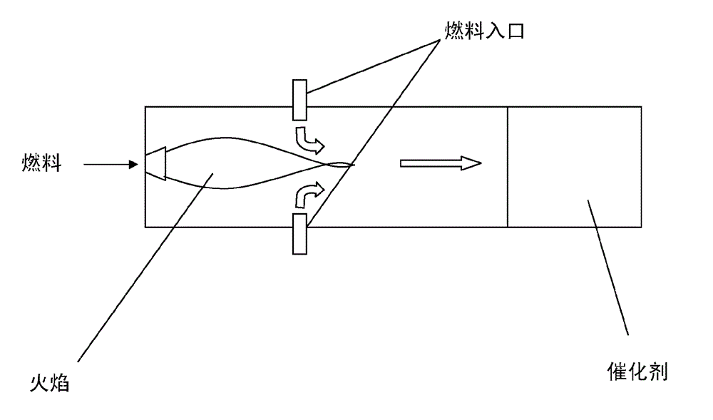
[0020] Referring to the drawings, in Figure 1 a prior art system according to US-6,223,537 is disclosed. The system includes a combustion chamber 10 having a generally double-walled pot-shaped configuration. The combustor 10 includes a combustor can 11 , a liner 12 and an upstream end 14 . The combustor can ...


PUM


Abstract

The present invention relates to a system for utilizing liquid fuels, such as diesel and gasoline, in a catalytic reactor for producing clean heat from the said fuel. In particular it relates to a fuel injection system for a catalytic burner (310, 313). It comprises preheating means (308', 309, 315; FT) for preheating the catalytic burner (310, 313) and primary fuel supply means (307) for supplying fuel to the catalytic burner (310, 313). The preheating means (308', 309, 315; FT) and the primary fuel supply means (307) are provided in separate compartments (310, 312), said compartments being connected with each other via a channel (CH).

Description

technical field [0001] The present invention relates to a system for utilizing liquid fuels such as diesel and gasoline in a catalytic reactor in order to generate clean heat from said fuel. Background technique [0002] Conventional fuel fired heaters utilize flame combustion to generate heat, a process associated with the generation of both particulates (soot, ash) and chemical emissions (CO, NOx), all of which are harmful to the environment . [0003] By replacing the flame combustion system with a catalytic oxidation system, fuel related emissions can be eliminated and at the same time the efficiency of the oxidation process is increased by lowering the temperature of the oxidation process (through increased air flow). The main feature of catalytic oxidation is that the process is not limited to lower air-fuel ratios, which feature leads to complete oxidation of all hydrocarbons and lower temperatures in the reaction zone, down to levels that hinder NOx production. [...

Claims


Application Information

Patent Timeline
Patent Type & Authority Applications(China)
IPC IPC(8): F23C13/02F23R3/40B60H1/22
CPCF23C13/02F23C13/06F23D11/44F23D11/446F23D2900/21002
Inventor B. 林德斯特雷姆D. 哈格斯特雷姆
Owner HEATING TECH IMPROVEMENT HLDG LTD
Why Eureka
Try Eureka