LED light source module
A technology of LED module and LED light source, applied in the field of LED lighting, to achieve the effect of prolonging service life, improving efficiency and overcoming LED flickering
- Summary
- Abstract
- Description
- Claims
- Application Information
AI Technical Summary
Problems solved by technology
Method used
Image
Examples
Embodiment 1
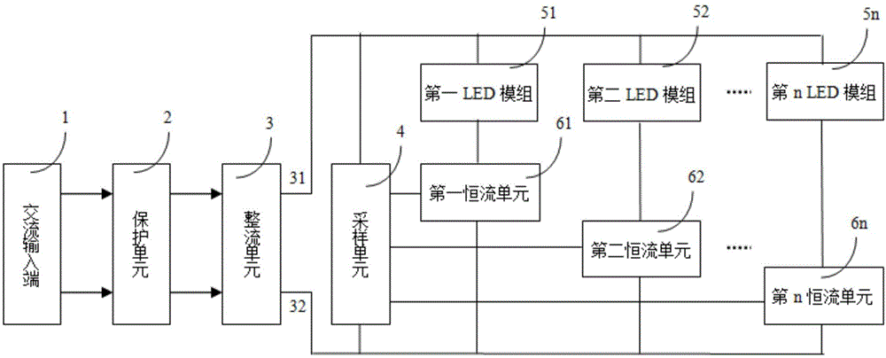
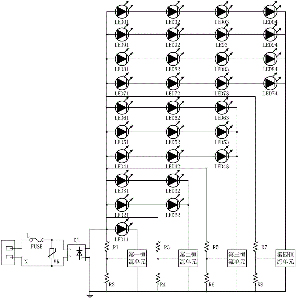
[0053] Such as figure 2 As shown, the protection unit 2 in this example is composed of a fuse F and a varistor VR. The fuse F is connected in series to the phase line L of the AC input terminal 1, and the varistor VR is connected in parallel to the phase line L and the neutral line N of the AC input terminal 1. between. The protection unit 2 is connected to the rectification unit 3 formed by the full-wave rectification circuit D1, and the output end of the rectification unit 3 is connected in parallel with 4 branches.
[0054]The first branch is composed of the first LED module and the first constant current unit in series. The first LED module is composed of one LED11, the positive end of which is connected to the positive pole of the rectification circuit D1, and the negative end is connected to the rectification circuit through the first constant current unit. D1 negative pole. In this example, the sampling is composed of a resistor network, including resistors R1 ~ R8. ...
Embodiment 2
[0058] image 3 The schematic diagram of the circuit of this example is shown, and it can be seen that this example is the same as that of Example 1 except that the LED module structure and its connection method are different from Example 1. The following only describes the structure of the LED module with four branch circuits. For other structures and their working process, please refer to the description of Embodiment 1, which will not be repeated here. The first LED module in the first branch of this example is composed of one LED31, the positive terminal of the first LED module is connected to the positive pole of the rectifier circuit D1, and the negative terminal of the first LED module is connected to the rectifier circuit through the first constant current unit D1 negative pole. The second LED module in the second branch of this example includes 4 LEDs in total, LED31, LED32, LED21, and LED22. When the first constant current unit is turned off, these 4 LEDs form a 2×...
Embodiment 3
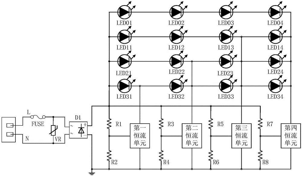
[0062] Such as Figure 4 As shown, the circuit schematic diagram of this example is compared with that of Example 2. The connection mode of each LED module has been further optimized. The four LED modules in the four branches are composed of 16 LEDs and adopt a 4×4 matrix topology. . The first LED module in this example is composed of a 1×4 array composed of 4 LEDs connected in parallel, namely LED01, LED11, LED21 and LED31. The second LED module in this example is composed of a 2×4 array composed of 8 LEDs connected in series and parallel, including LED01, LED11, LED21, LED31, LED02, LED12, LED22, and LED32. The third LED module in this example is composed of LED01, LED11, LED21, LED31, LED02, LED12, LED22, LED32, LED03, LED13, LED23, LED33, a total of 12 LEDs connected in series and parallel to form a 3×4 array. The LED module consists of LED01, LED11, LED21, LED31, LED02, LED12, LED22, LED32, LED03, LED13, LED23, LED33, LED04, LED14, LED24, LED34, a total of 16 LEDs are c...
PUM
 Abstract
Description
Claims
Application Information
 - Generate Ideas
- Intellectual Property
- Life Sciences
- Materials
- Tech Scout
- Unparalleled Data Quality
- Higher Quality Content
- 60% Fewer Hallucinations
Browse by: Latest US Patents, China's latest patents, Technical Efficacy Thesaurus, Application Domain, Technology Topic, Popular Technical Reports.
© 2025 PatSnap. All rights reserved.Legal|Privacy policy|Modern Slavery Act Transparency Statement|Sitemap|About US| Contact US: help@patsnap.com


