
Channel state selection method and device based on ternary coding

A channel state and encoding technology, applied in the direction of sensors, electrical components, sensor components, etc., can solve the problems of unexplained multi-channel three-state encoding selection, signal destruction, nonlinear distortion, etc., to save hardware power consumption and save hardware resources, the effect of small total harmonic distortion

Active Publication Date: 2015-04-29
SUZHOU SONAVOX ELECTRONICS
View PDF9 Cites 8 Cited by
  • Summary
  • Abstract
  • Description
  • Claims
  • Application Information

AI Technical Summary

Problems solved by technology

The digital system based on 1-bit Δ-Σ modulation has the following defects while having the above-mentioned many advantages: ①It is sensitive to clock jitter, and it is easy to introduce nonlinear distortion due to clock jitter; ②In order to maintain the stability of the modulation structure The allowable dynamic range of the input signal is small; ③ requires a high switching rate, and the power MOSFET tube will generate more nonlinear distortion components in the process of driving the speaker load for high-speed switching, and will also cause MOSFET Increased tube heating, increased temperature and reduced efficiency
A three-state driving method is proposed in US patent US2014169577, but this patent does not explain how to select multi-channel three-state encoding, so it is impossible to avoid the influence of the deviation between multi-channels on the degradation of the system signal-to-noise ratio
[0007] The traditional three-state unit selection strategy is to divide the input signal into positive input and non-positive input, and then adopt the traditional two-state unit-based dynamic mismatch shaping selection strategy for the two types of input. This strategy can be inherited from the original Minor changes are made on the basis of the design, and the structure is simple, but the signal-to-noise ratio of the output signal after shaping is low, and it changes with frequency changes
Although this traditional three-state selection strategy reduces the resource occupation of hardware implementation, it also sacrifices the output signal-to-noise ratio performance
US Patent US20120057727 proposes a strategy of using channel average and time average to select tri-state units, but this strategy has two defects: (1) This method only gives the selection when the input signal is close to 0 The strategy does not give the selection strategy under other input conditions; (2) The time averaging strategy method will destroy the original signal and easily introduce harmonic distortion

Method used


Image

  • Channel state selection method and device based on ternary coding
  • Channel state selection method and device based on ternary coding
  • Channel state selection method and device based on ternary coding

Examples


Embodiment 1

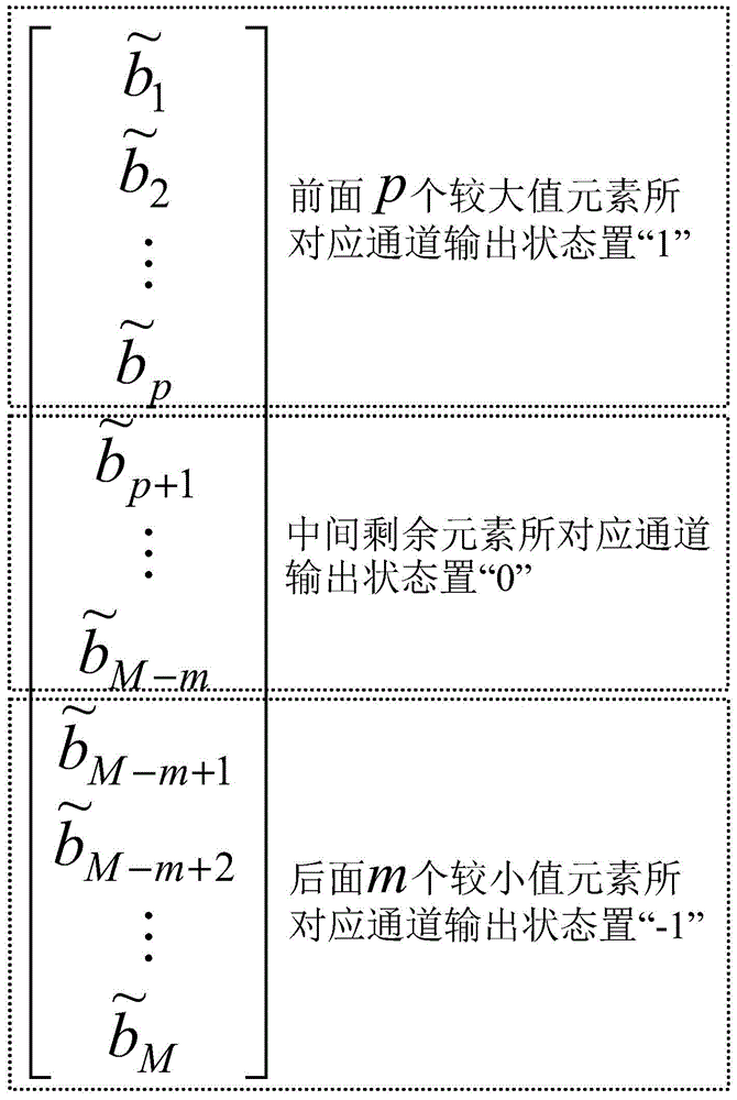
[0110] In this embodiment, Table 3(a) shows the relationship between the output and input of the channel state selection method based on three-state coding proposed by the present invention in 8 channels, while Table 3(b) also shows the traditional method based on The relationship between the output and the input of the channel state selection method of the VFMS improved algorithm. The channel selection strategy of the traditional channel state selection method based on the VFMS improved algorithm is: (1) for the M channel feedback signal b=[b 1 ,b 2 ,L,b M ] to deduce; (2) When x≥0, set the channel corresponding to the first x elements with the largest feedback signal b to "1", and set the channel corresponding to the other remaining elements to "0"; (3) When x<0 , set the channels corresponding to the last -x elements with the smallest feedback signal b to "-1", and the channels corresponding to the other remaining elements to "0"; (4) Arrange the output signals of all cha...

Embodiment 2

[0118] In this embodiment, the correspondence between the channel state selection method based on the three-state coding proposed by the present invention and the traditional channel state selection method based on the VFMS improved algorithm is given for the single-channel signal-to-noise ratio as the input signal frequency and amplitude change relationship, such as Figure 12 As shown in , it also gives the spectrogram of the single-channel signal reshaped generated by the two methods when the input signal is 1KHz and the input signal amplitude is the normalized amplitude -6dB, as shown in Figure 13 shown. From Figure 12 (a) It can be seen that the single-channel SNR of the traditional channel state selection method based on the VFMS improved algorithm increases with the increase of the input signal frequency, but at all frequency points, its SNR level is lower than that of the present invention The signal-to-noise ratio of the proposed channel state selection method bas...


PUM


Abstract

The invention discloses a channel state selection method and device based on ternary coding. The method includes the steps that a sound source signal is modulated into (2L+1) electric-level-grade quantitative signals x, mapping transformation is performed on the quantitative signals x so that control signals p, m and z can be generated, selection processing is performed on the control signals p, m and z and an M channel feedback signal b, then, an M channel state vector signal y is output, shape-correction processing is performed on the state vector signal y, then, the M channel feedback signal b is generated, and the state vector signal y completes electric-acoustic conversion through a multi-channel power amplifier and an energy converter. The device comprises a modulator module, a mapping module, a selection module, a shape-correction module, the multi-channel digital power amplifier and a loudspeaker array or a multi-voice-coil loudspeaker unit which are all connected in sequence. Through the method and device, hardware resource expenditure can be effectively reduced, hardware electric power consumption can be reduced, system stability is enhanced, the amplitude of an output signal can further be improved, conversion efficiency is improved, and meanwhile high signal-to-noise ratio output capacity is achieved.

Description

technical field [0001] The present invention relates to a digital loudspeaker encoding method and device, in particular to a channel state selection method and device based on three-state encoding. Background technique [0002] With the rapid development of VLSI manufacturing technology, the design and manufacture of loudspeaker systems, the leading product in the electro-acoustic industry, are gradually developing in the direction of low power consumption, miniaturization, and portability. In recent years, the semi-digital loudspeaker system driven by the wave of digitalization has successfully solved the power consumption and heat generation problems due to its use of Pulse Width Modulation (PWM) Class D power amplifier drive technology, and greatly improved the overall The electroacoustic conversion efficiency of the system. However, the rear stage of the semi-digital loudspeaker system still needs to rely on a bulky LC low-pass analog filter to filter out the out-of-ban...

Claims


Application Information

Patent Timeline
IPC IPC(8): H04R23/00
CPCH04R23/00
Inventor 蔡野锋马登永
Owner SUZHOU SONAVOX ELECTRONICS
Learn More