
Automatic-focusing wireless charging belt system and full-automatic laying device for wireless charging belt

A wireless charging and auto-focusing technology, which is applied in electromagnetic wave systems, battery circuit devices, current collectors, etc., can solve the problems of complex implementation, low charging efficiency, and damage to human body caused by microwaves, and achieve simple and convenient laying construction and high charging efficiency Effect

Pending Publication Date: 2015-04-29
刘跃进
View PDF9 Cites 14 Cited by
  • Summary
  • Abstract
  • Description
  • Claims
  • Application Information

AI Technical Summary

Problems solved by technology

The three technologies have their own advantages and disadvantages. Microwave technology can transmit energy at a relatively long distance, but high-power microwaves have certain damage to the human body; electromagnetic resonance technology can transmit energy at a distance of tens of centimeters, but the transmission power is relatively free of electromagnetic coupling. Large technology; electromagnetic coupling technology is more suitable for high-power energy transmission, but the environment used is close distance: the distance between the charging transmitter and receiver is less than tens of millimeters
Since the charging efficiency of the existing wireless non-contact charging technology is inversely proportional to the square of the distance between the charging transmitter and the receiver, the farther the distance is, the lower the efficiency is, and the distance between the site of an electric vehicle and the road is generally 200-500 mm Therefore, the charging efficiency of the existing wireless non-contact charging technology in the field of electric vehicles is relatively low
It was also proposed to install a height-adjustable bracket under the chassis of the car to reduce the distance between the receiving antenna and the road. This method is acceptable for non-contact charging in the parking lot when the electric car is stationary, but for high-speed For electric vehicles in motion, if the distance between the receiving antenna and the road is too small, any bumps will cause serious safety hazards
In addition, if the existing wireless non-contact charging technology is directly used in the field of electric vehicles, it will cause serious electromagnetic radiation and energy waste.
Someone once proposed to use the pressure sensor to detect the passage of the vehicle before turning on the charging current. However, it still generates electromagnetic radiation and wastes charging energy for a large number of non-electric vehicles or vehicles that do not need to be charged.
Moreover, the direct application of existing wireless non-contact charging technology solutions in the field of electric vehicles still has a series of problems such as complex implementation and construction, which is not conducive to large-scale and large-area construction.
To sum up, the shortcomings and deficiencies of existing wireless non-contact charging technology include: 1. Low charging efficiency; Cause electromagnetic radiation and energy waste

Method used


Image

  • Automatic-focusing wireless charging belt system and full-automatic laying device for wireless charging belt
  • Automatic-focusing wireless charging belt system and full-automatic laying device for wireless charging belt
  • Automatic-focusing wireless charging belt system and full-automatic laying device for wireless charging belt

Examples


Embodiment Construction

[0025] The present invention will be described in detail below in conjunction with the accompanying drawings and practical examples.

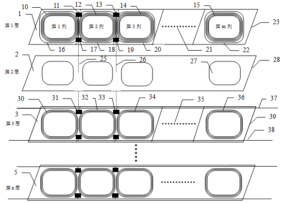
[0026] figure 1 A schematic diagram showing the layered structure of the electromagnetic auto-focus wireless charging belt in the present invention, figure 1 shows a control module that contains m transmit antenna arrays and a layered anatomical architecture of n layers: from top to bottom, the top is the first layer (1), and the bottom is the nth layer (5); The layer is the emission layer (1), including m charging current transmitting antenna columns (10, 12, 14, 15), m control signal transmitting and receiving antenna columns (16, 18, 20, 22), and m capacitor plates (23 ), and the control unit parts (11, 13, 17, 19) of 2m antenna array controllers, only the 1st column, the 2nd column, the 3rd column and the mth column are shown in the figure, and the other columns use ellipsis (21) Omit; the 2nd layer is insulating plate layer (2), and the ...


PUM


Abstract

The invention provides an electromagnetic automatic-focusing wireless charging belt technology for charging an electric vehicle during running, a wireless charging belt control system, a technology implementation method, and a full-automatic laying construction device and method for the wireless charging belt. The wireless charging belt system comprises a wireless charging belt, a charging belt controller, a charging belt receiver, a charging card and a charging management background. The wireless charging belt is a belt-shaped object sealed by a high-strength plastic or rubber or alloy sealed casing, the width of the belt-shaped object is 20-350 cm, the thickness of the belt-shaped object is smaller than 5 cm, and the longest length of the belt-shaped object can be thousands of kilometers. The wireless charging belt is characterized in that the latest techniques of dynamic electromagnetic emission arrays and static electromagnetic emission arrays are firstly adopted, the wireless charging belt automatically focuses electromagnetic charging flows on a receiving antenna which is positioned at the bottom of the electric vehicle or in a chargeable tire, so that the wireless charging efficiency is effectively improved. The charging belt has the functions of water prevention, dust prevention, water seepage prevention, and ventilation, the charging belt is ultrathin, and the charging belt can be laid by the full-automatic laying construction device fully automatically.

Description

technical field [0001] The present invention provides a brand-new electromagnetic auto-focusing wireless charging belt technology for charging electric vehicles at high speeds, a wireless charging belt control system and a technical implementation plan, as well as the laying construction equipment and laying construction method of the wireless charging belt , which belongs to the field of new energy vehicles. Background technique [0002] With the development of electric vehicle technology, the charging problem of electric vehicles will become increasingly prominent, and even become the throat that restricts the popularization of electric vehicles. Charging piles can solve the problem of charging electric vehicles while parked, but due to the relatively long charging time, it is difficult to solve the problem of charging during travel. The wireless non-contact charging technology has been realized in the laboratory more than ten years ago, and the short-distance non-contact...

Claims


Application Information

Patent Timeline
IPC IPC(8): H02J7/00H02J17/00E01C23/06E01C23/16H02J50/20
CPCH02J5/005H02J7/025E01C23/06E01C23/16
Inventor 刘跃进
Owner 刘跃进
Learn More