
Spraying device with quick drying structure for machining lampshade of ceiling lamp

A chandelier lampshade and fast drying technology, which is applied in spraying devices, devices for coating liquid on the surface, coatings, etc., can solve the problems of the decline in the aesthetics of the chandelier lampshade and the unevenness of the surface of the chandelier lampshade

Inactive Publication Date: 2021-08-27
重庆惠瑞才翔智能装备有限公司
View PDF0 Cites 0 Cited by
  • Summary
  • Abstract
  • Description
  • Claims
  • Application Information

AI Technical Summary

Problems solved by technology

[0004] The purpose of the present invention is to provide a spraying device with a fast drying structure for processing a chandelier lampshade, so as to solve the problem that the existing spraying device proposed in the above-mentioned background technology tends to cause the sprayed protective paint to be uniform enough when spraying the chandelier lampshade, thereby It leads to the decline of the aesthetics of the chandelier lampshade, and it is also easy to cause the problem of uneven surface of the chandelier lampshade

Method used


Image

  • Spraying device with quick drying structure for machining lampshade of ceiling lamp
  • Spraying device with quick drying structure for machining lampshade of ceiling lamp
  • Spraying device with quick drying structure for machining lampshade of ceiling lamp

Examples


Embodiment Construction

[0029] The following will clearly and completely describe the technical solutions in the embodiments of the present invention with reference to the accompanying drawings in the embodiments of the present invention. Obviously, the described embodiments are only some, not all, embodiments of the present invention.

[0030] In the description of the present invention, unless otherwise stated, the meaning of "plurality" is two or more; the terms "upper", "lower", "left", "right", "inner", "outer" , "front end", "rear end", "head", "tail", etc. indicate the orientation or positional relationship based on the orientation or positional relationship shown in the drawings, and are only for the convenience of describing the present invention and simplifying the description, rather than indicates or implies that the device or element referred to must have a particular orientation, be constructed and operate in a particular orientation, and therefore should not be construed as limiting the...


PUM


Abstract

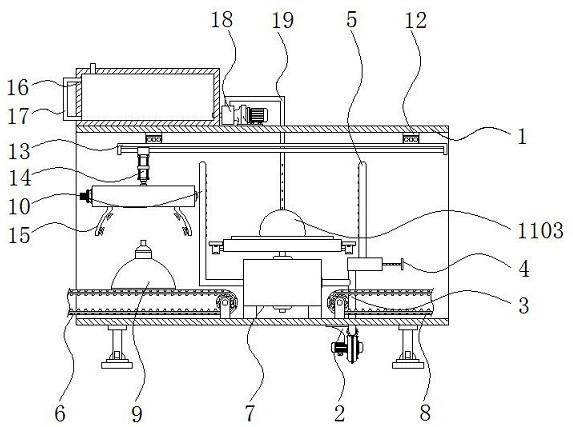
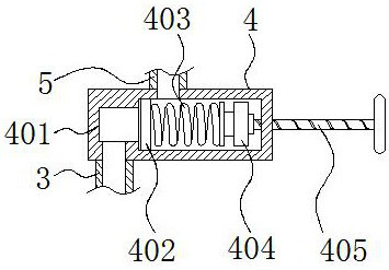
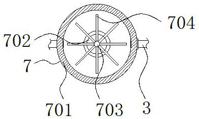
The invention relates to a spraying device with a quick drying structure for machining a lampshade of a ceiling lamp. The spraying device comprises an equipment shell and a multi-section hydraulic cylinder, a first draught fan is installed at the lower end of the equipment shell, a connecting pipe is connected to the front end of the first draught fan, and a pressure relief mechanism is connected to the upper end of the connecting pipe; and a first belt conveyor, a rotating mechanism and a second belt conveyor are sequentially arranged at the lower end of the interior of the equipment shell from left to right, a second air spraying pipe is connected to one side of the rotating mechanism, a placing mechanism is connected to the upper end of the rotating mechanism, and a first electric sliding rail is installed on the upper wall of the interior of the equipment shell. The spraying device with the quick drying structure for machining the lampshade of the ceiling lamp has the beneficial effects that the air pressure in the connecting pipe can be kept at a constant value through the pressure relief mechanism, so that a rotating shaft can be driven to rotate at a constant speed when a fan blade plate is blown by constant-pressure airflow, and the equipment can spray the lampshade of the ceiling lamp more uniformly.

Description

technical field [0001] The invention relates to the technical field of chandelier lampshade processing, in particular to a spraying device with a fast drying structure for processing chandelier lampshades. Background technique [0002] The chandelier is a high-end decorative lighting that is hung on the indoor ceiling. All the hanging lamps are classified into the chandelier category. The chandelier is usually equipped with a lampshade on the upper end, so that the chandelier can be protected from dust. The chandelier lampshade needs to be processed during processing. Spray a protective varnish on the surface of the chandelier shade using a spraying device. [0003] When the existing spraying device sprays the chandelier lampshade, the sprayed protective paint is likely to be uniform enough, thereby resulting in a decrease in the aesthetics of the chandelier lampshade, and also easily causing the problem of uneven surface of the chandelier lampshade. Contents of the invent...

Claims


Application Information

Patent Timeline
Patent Type & Authority Applications(China)
IPC IPC(8): B05B16/20B05B13/02B05D3/04
CPCB05B13/0228B05D3/0406B05B16/20
Inventor 谢晶晶黄梓航符晟
Owner 重庆惠瑞才翔智能装备有限公司
Learn More