Magnetic cores, chip inductor with magnetic cores and manufacturing method

A manufacturing method and magnetic core technology, applied in the direction of inductance with magnetic core, inductance/transformer/magnet manufacturing, transformer/inductor magnetic core, etc., can solve the damage of ferric oxide material, low product yield, vibration And other issues

Inactive Publication Date: 2015-04-29
CHEERING SUN APPLIED MATERIALS
View PDF5 Cites 0 Cited by
  • Summary
  • Abstract
  • Description
  • Claims
  • Application Information

AI Technical Summary

Problems solved by technology

However, the material of ferric oxide is usually made of powder particles pressed or sintered to form a substrate, and the material is very brittle and easy to break
[0005] If turning is used in the production process, on the one hand, it is not easy to modify the details, and the processed shape is limited to a circle; therefore, the volume of the finished product is not easy to reduce, and the shape is limited, and the processing speed is limited, so the production capacity cannot be increased
If another grinding method is used, it will also be unable to produce in large quantities due to the low efficiency of the grinding machine
Finally, whether it is lathe or grinding, there will be friction between the processed items and cause a certain degree of vibration
If the processed item is made of the aforementioned ferric oxide material, this type of processing is likely to cause damage to the ferric oxide material
[0006] Severely cracked substrates are unusable. Even slight cracks will form air gaps between magnetically permeable materials and greatly increase reluctance, which will greatly reduce the predetermined magnetically permeable effect and become inferior products. The product yield rate will be low, which will make The above-mentioned slow processing problem becomes more serious
[0007] From the situation mentioned above, it can be seen that the previous manufacturing method of inductor cores cannot greatly reduce the volume of the core, which does not conform to the trend of the miniaturization of electronic components; the shape of the core is limited and there is no flexibility in selection, which limits the application of inductors. range; in addition, due to the need to grind one by one, mass production cannot be done; at the same time, due to the vibration problem during turning and polishing, the product yield cannot be improved

Method used


Image

  • Magnetic cores, chip inductor with magnetic cores and manufacturing method
  • Magnetic cores, chip inductor with magnetic cores and manufacturing method
  • Magnetic cores, chip inductor with magnetic cores and manufacturing method

Examples


Embodiment Construction

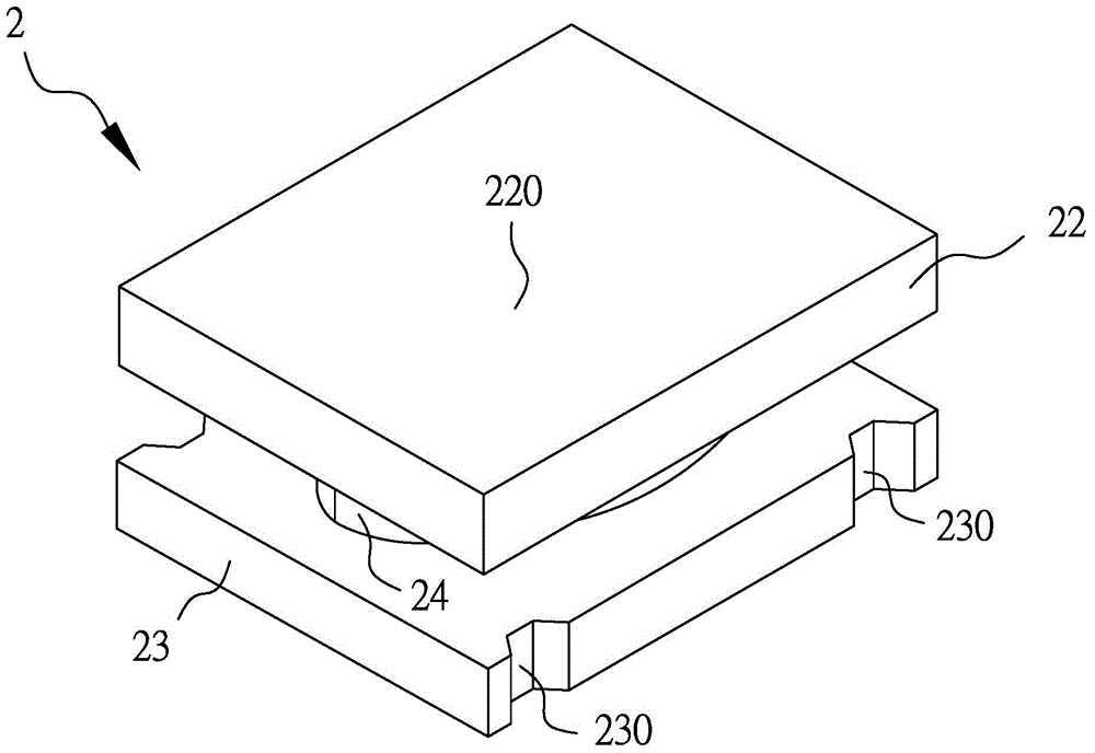
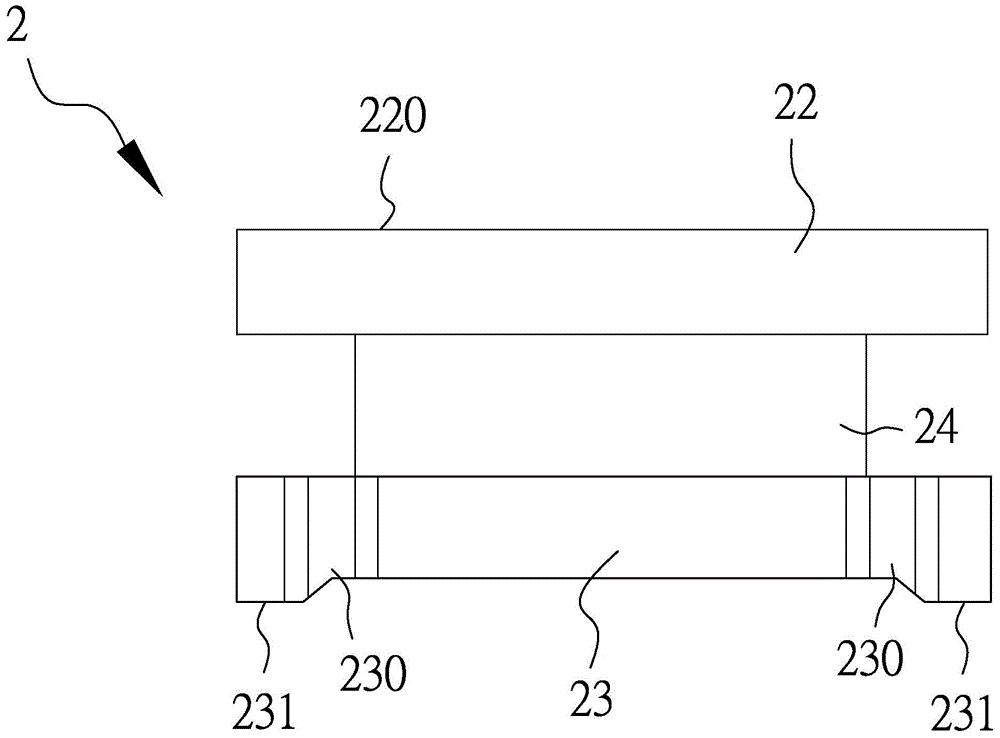
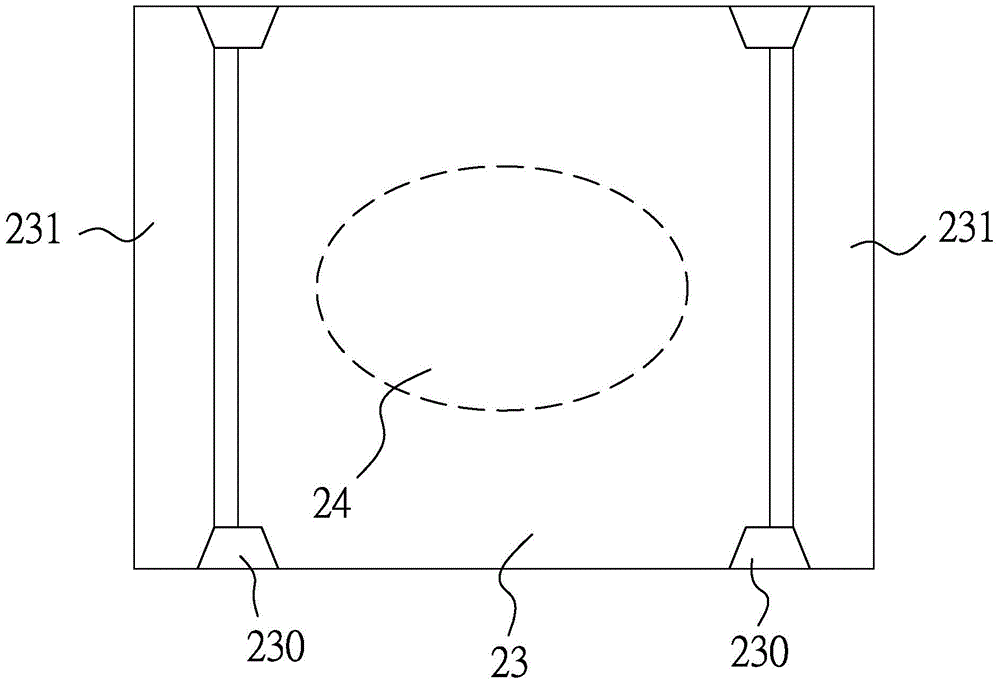
[0030] Magnetic core of the present invention, chip inductor with magnetic core and manufacturing method thereof, the magnetic core of the first preferred embodiment of the present invention is as Figure 1 to Figure 3 As shown, make as Figure 1-3 The shown magnetic core 2, the magnetic core 2 is composed of non-conductive ferromagnetic material such as ferric oxide, and the side view is like a letter I. The basic structure includes a top 22, a base 23, and a depression connecting the top 22 and the base 23 Winding part 24. Among them such as image 3 As shown in the perspective view of the bottom, the outlines of the top 22 and the base 23 are larger than the outline of the concave winding portion 24 (broken oval line). The uppermost surface of the top 22 is an adsorption plane 220 , which is used to facilitate the adsorption and movement of the suction nozzle of the mechanical arm when the inductance element is finally formed and surface-mounted to the circuit board.

[...


PUM


Abstract

The invention relates to a manufacturing method of a chip inductor with magnetic cores. The manufacturing method comprises the following steps: a) jointly injecting a non-conductive ferromagnetic matter and a volatile solvent to a die which is provided with a plurality of magnetic core mould cavities so as to form a plurality of magnetic core original shapes; b) after the magnetic core original shapes are condensed on the magnetic core mould cavities, demoulding; c) warming to be higher than vaporization temperature of the volatile solvent, wherein the volatile solvent in the magnetic core original shapes is vaporized to form a plurality of magnetic cores and a sunken winding part is formed on each magnetic core; d) respectively winding windings to the sunken winding parts of the magnetic cores. The chip inductor with the magnetic cores, which is small in volume and high in manufacturing yield, is manufactured by virtue of the method.

Description

【Technical field】 [0001] The invention relates to a magnetic core, a chip inductor with a magnetic core and a manufacturing method thereof. 【Background technique】 [0002] As a self-inductive electronic component, an inductor has many functional characteristics such as filtering, suppressing instantaneous current, alternating current, etc., reducing EMI noise and power conversion; therefore, it is widely used in the field of electronic circuits, such as oscillation, tuning, coupling , filtering, delay and deflection circuits. Its manufacturing method is usually formed by winding a coil on an iron core. When current flows through the coil, according to Faraday's law of electromagnetic induction, the coil will generate an electromotive force to resist this change, which is the so-called hysteresis. [0003] The structure of the inductor includes a coil and an iron core. After the coil is energized, the magnetic force lines are formed. The magnetic force lines diverge from the...

Claims


Application Information

Patent Timeline
IPC IPC(8): H01F41/00H01F41/02H01F17/04H01F27/24
Inventor 庄弘毅曾国书
Owner CHEERING SUN APPLIED MATERIALS
Why Eureka
Try Eureka