
A method for measuring the angle of boresight of a spatially distributed camera

A camera boresight and test method technology, applied in the field of aerospace optical remote sensors, can solve problems such as difficulty and large scale, and achieve the effects of improving test accuracy, shortening test cycle, and saving test costs

Active Publication Date: 2017-03-15
BEIJING RES INST OF SPATIAL MECHANICAL & ELECTRICAL TECH
View PDF6 Cites 0 Cited by
  • Summary
  • Abstract
  • Description
  • Claims
  • Application Information

AI Technical Summary

Problems solved by technology

If a set of high-precision, large-capacity four-dimensional testing equipment is developed, it will be very difficult and large-scale

Method used

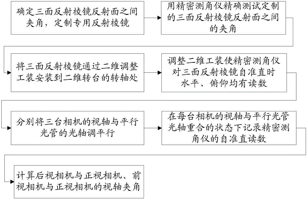

Image

  • A method for measuring the angle of boresight of a spatially distributed camera
  • A method for measuring the angle of boresight of a spatially distributed camera
  • A method for measuring the angle of boresight of a spatially distributed camera

Examples


Embodiment Construction

[0022] The basic idea of ​​the present invention is to use a three-sided reflecting prism and a high-precision precision goniometer to realize the angle test of the visual axis of a spatially distributed camera. The installation location of the test equipment such as Figure 4 As shown, the specific implementation is as follows:

[0023] Step (1) Determine the angle between the two adjacent reflective surfaces of the three-sided reflective prism 3 so that the angle between the adjacent reflective surfaces of the three-sided reflective prism 3 is 180°-Φ; where Φ is the phase of the three-line array camera 2 under test Design value of the angle of sight of adjacent camera;

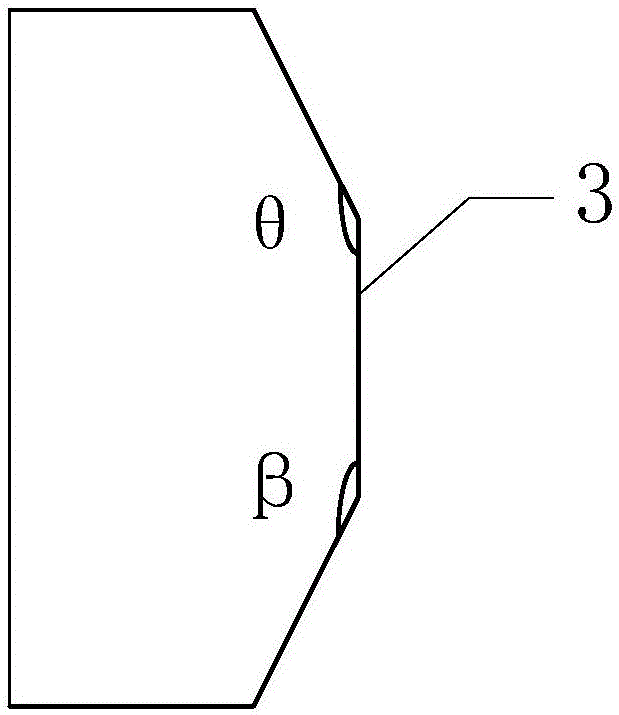
[0024] Step (2) Use the precision goniometer 1 to test the actual values ​​of the two included angles θ and β of the adjacent reflective surfaces of the three-sided reflective prism 3, such as image 3 As shown, θ and β are the actual test values ​​of the included angle between adjacent reflecting surfaces, and ...


PUM


Abstract

A method for testing the included angle of boresight of spatially distributed cameras, using a high-precision two-dimensional turntable, a custom-made three-sided reflective prism, a precision goniometer, and a high-precision positioning and error compensation device to build a test system. Through the two-dimensional adjustment tooling, the customized three-sided reflective prism is installed on the pitch rotation axis end of the high-precision two-dimensional turntable, and the three-sided reflective prism is self-collimated with a precision goniometer. Adjust the two-dimensional adjustment tooling so that the precision goniometer has a visual number when it is self-collimating to the three mirrors. Rotate the turntable and adjust the spatial position of the collimator so that the viewing axis of each camera is adjusted to be parallel to the optical axis of the collimator in turn, store the measurement data of the self-collimation of the three-sided mirror by the precision goniometer, and calculate the viewing angle of the camera to be tested. axis angle. This technology can be applied to the boresight angle test of spatially distributed remote sensing cameras, and can achieve a test accuracy better than 3″. It has been applied in the integration test of three-line array cameras and has passed the on-orbit test.

Description

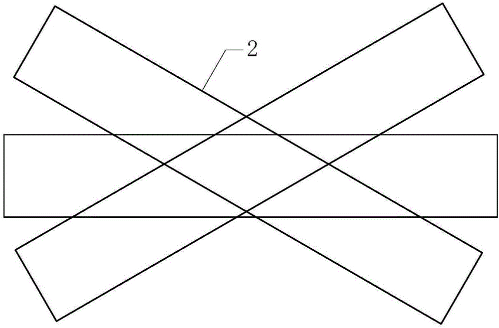
Technical field [0001] The invention belongs to the technical field of aerospace optical remote sensors, and is suitable for precision testing of the angle of the visual axis of a spatially distributed camera such as a stereo surveying and mapping camera. Background technique [0002] Transmission type large-scale stereo surveying and mapping cameras are usually in the form of two-line or three-line arrays, composed of two or three surveying and mapping cameras, and the two or three cameras are distributed at an angle in space. This type of phase mechanism requires precise calibration of the intersection angle between two or three cameras during camera development, and its accuracy requirements are very high, often requiring calibration accuracy within 5". [0003] Take a three-line scan camera composed of three cameras as an example. The three cameras are not coplanar and form a spatial relationship. The configuration diagram of the three-line scan camera is as follows figure 2 Sh...

Claims


Application Information

Patent Timeline
Patent Type & Authority Patents(China)
IPC IPC(8): G03B43/00
Inventor 李重阳马丽娜张继友岳丽清王东杰王聪
Owner BEIJING RES INST OF SPATIAL MECHANICAL & ELECTRICAL TECH
Learn More