
Gamma emitter position distinguishing system and method

A technology of gamma radiation and source location, applied in the field of radiation monitoring system, can solve the problems of limited detection accuracy, inability to adapt to electromagnetic environment, single information content, etc.

Inactive Publication Date: 2015-04-29
HEFEI UNIV OF TECH
View PDF7 Cites 7 Cited by
  • Summary
  • Abstract
  • Description
  • Claims
  • Application Information

AI Technical Summary

Problems solved by technology

The artificial identification method uses human knowledge, experience, analysis and reasoning, and makes judgments on radiation information, which cannot adapt to the complex electromagnetic environment; in the complex geographical environment in the field, the artificial identification method is also greatly restricted
When the position of the radiation source is uncertain, using traditional manual methods to detect is a huge project. At the same time, due to the high-risk nature of the radiation source, long-term reconnaissance and detection put forward requirements for the safety of the inspectors.
In anti-terrorism operations, due to the complex background environment, manual inspection cannot meet the operational needs
The intelligent recognition method is generally more complicated, and the detection period is too long, which cannot meet the real-time detection; at the same time, the intelligent recognition method puts forward higher requirements for the computer system, which is not easy to realize
[0003] Due to the limitations of detection methods, existing methods such as manual identification methods, traditional data processing identification methods, and intelligent identification methods have limited detection accuracy, and in the case of weak radiation signals, it is easy to cause misjudgment; and the information obtained is relatively single. Only the radiation intensity information of the radiation source can be provided, but the spatial information around the radiation source cannot be provided

Method used


Image

  • Gamma emitter position distinguishing system and method
  • Gamma emitter position distinguishing system and method
  • Gamma emitter position distinguishing system and method

Examples


Embodiment Construction

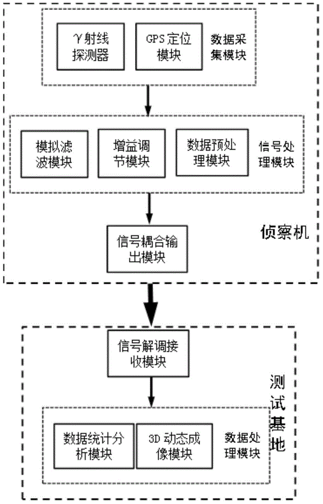
[0042] In this example, if figure 1 As shown, a gamma radiation source position discrimination system includes: a reconnaissance plane and a test base; the reconnaissance plane includes: a data acquisition module, a signal processing module and a signal coupling output module; the test base includes a signal demodulation receiving module and a data processing module;

[0043] The data acquisition module is composed of gamma ray detector and GPS global positioning module. When there is a gamma radiation source in the detected area, the radiation source will emit gamma signals to the surrounding space, and the signal intensity will be distributed in a spherical shape with the radiation source as the center of the sphere. In the same horizontal plane, the radiation intensity will be in a circle with the center of the strongest signal point. shape distribution, the projection of the strongest signal point on the ground is the radiation source coordinates.

[0044] In the system, ...


PUM


Abstract

The invention discloses a gamma emitter position distinguishing system and method. The system is mainly characterized by comprising a reconnaissance plane and a test site; the reconnaissance plane comprises a data acquisition module, a signal processing module and a signal coupling output module; the test site comprises a signal demodulation receiving module and a data processing module; the data acquisition module is composed of a gamma ray detector and a GPS (global positioning system) module; the signal processing module is composed of a gain adjustment module, an analog filtering module and a data preprocessing module; the data processing module is composed of a data analysis and judgment module and a 3D (three-dimensional) dynamic simulation module. By the system and method, position detection of a gamma emitter can be realized quickly, and detection efficiency and detection accuracy are improved.

Description

technical field [0001] The invention belongs to the technical field of radiation monitoring systems, in particular to a gamma radiation source position detection system. Background technique [0002] With the continuous advancement of science and technology, people are more and more affected by radiation in their daily life. Therefore, the detection of radiation sources is becoming more and more important. At present, there are many researches on radiation source detection methods, mainly including artificial identification methods, traditional data processing identification methods, intelligent identification methods, etc. The artificial identification method uses human knowledge, experience, analysis and reasoning, and makes judgments on the radiation information, which cannot adapt to the complex electromagnetic environment; in the complex geographical environment in the field, the artificial identification method is also greatly restricted. When the location of the rad...

Claims


Application Information

Patent Timeline
IPC IPC(8): G01T1/00G01T1/29
Inventor 郭志强潘淑豪徐进章李媛
Owner HEFEI UNIV OF TECH
Learn More