
Multistage fracturing tool pipe column of continuous oil pipe and construction method

A tool pipe and oil pipe technology, applied in the field of oil and gas field construction, can solve the problems of low construction efficiency, sand production in the formation, long construction period, etc., and achieve the effect of shortening the construction time

Inactive Publication Date: 2015-04-29
JEREH ENERGY SERVICES
View PDF7 Cites 94 Cited by
  • Summary
  • Abstract
  • Description
  • Claims
  • Application Information

AI Technical Summary

Problems solved by technology

This process has a long construction period, the fracturing fluid does not flow back in time to pollute the oil layer, a long horizontal section is required for sand filling, and it is difficult to flush the sand plug.
[0004] The other is to use ordinary tubing to drag the packer to fracturing layer by layer. After a stage of fracturing, the formation pressure is the pressure at which the pump is stopped. Therefore, it is necessary to control the blowout pressure through the oil nozzle, and the pipe string can be dragged to the lower layer section until the formation pressure drops to zero, resulting in long construction period, low construction efficiency, and untimely flowback of fracturing fluid will pollute the oil layer

Method used


Image

  • Multistage fracturing tool pipe column of continuous oil pipe and construction method
  • Multistage fracturing tool pipe column of continuous oil pipe and construction method
  • Multistage fracturing tool pipe column of continuous oil pipe and construction method

Examples


Embodiment Construction

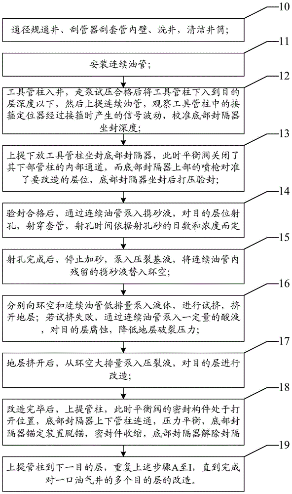
[0037] The first core of the present invention is to disclose a coiled tubing multi-stage fracturing tool string to achieve the purpose of shortening the time of fracturing acidification; the second core of the present invention is to disclose a coiled tubing multi-stage fracturing tool string Construction method. Hereinafter, an embodiment will be described with reference to the drawings. In addition, the examples shown below do not limit the content of the invention described in the claims in any way. In addition, all the contents of the configurations shown in the following embodiments are not limited to be essential to the solutions of the invention described in the claims.

[0038] Such as figure 1 with figure 2 As shown, the coiled tubing multi-stage fracturing tool string includes a joint 1, a hand 2, a centralizer 3, a spray gun 4, a balance valve 5, a bottom packer 6, a friction nipple 7, a collar positioner 8 and a pilot Shoe 9, wherein, connecting hand 1, throw...


PUM


Abstract

The embodiment of the invention discloses a multistage fracturing tool pipe column of a continuous oil pipe and a construction method. A contact, a releasing sub, a centralizer, a spray gun, a balance valve, a bottom packer, a friction pup joint, a collar locator and a guiding shoe are connected to form the tool pipe column, wherein the contact and a connecting oil pipe are connected and are positioned on the top end of the whole tool pipe column; the spray gun and the balance valve are positioned above the bottom packer; when the tool pipe column is subjected to setting, the internal channels of the upper pipe column and the lower pipe column of the bottom packer are packed by the balance valve; when the tool pipe column is lifted, the balance valve is used for communicating the internal channels of the upper pipe column and the lower pipe column of the bottom packer. Since the balance valve and the bottom packer are arranged, after the modification of one target layer is finished, a sealing construction member of the balance valve is positioned on an opening position when the fracturing tool pipe column is lifted, the upper pipe column and the lower pipe column of the bottom packer are communicated, pressure is balanced, and construction time is shortened.

Description

technical field [0001] The present invention relates to the technical field of oil and gas field construction, more specifically, relates to a coiled tubing multi-stage fracturing tool string and its construction method, which is especially suitable for fracturing and acidizing construction of oil and gas wells, and is especially suitable for tight sandstone oil and gas reservoirs and shale gas reservoirs. It is an effective transformation method for unconventional oil and gas reservoirs. Background technique [0002] Since many oil and gas reservoirs in my country have multiple production layers in the vertical direction, and most of them are thin interbeds, in order to obtain considerable oil and gas production, fracturing and acidizing is usually an important transformation measure to achieve oil and gas well stimulation. [0003] There are many methods at home and abroad to implement drag fracturing for wells completed with casing. One is to use the coiled tubing to run...

Claims


Application Information

Patent Timeline
IPC IPC(8): E21B43/26E21B43/114E21B43/27
CPCE21B43/114E21B43/26
Inventor 宁世品戴伟伟韩滔孟凡超梅鹏
Owner JEREH ENERGY SERVICES
Learn More