
Method for generating super-high giant magneto impedance effect on amorphous microwire

An amorphous microwire and giant magneto-impedance technology, which is applied in the field of amorphous microwire with extremely high giant magneto-impedance effect, can solve problems such as no related reports on amorphous microwire, and achieves easy repeatable annealing and simple equipment and process. , the effect of improving uniformity

Active Publication Date: 2015-04-29
HARBIN INST OF TECH
View PDF2 Cites 9 Cited by
  • Summary
  • Abstract
  • Description
  • Claims
  • Application Information

AI Technical Summary

Problems solved by technology

At present, there are no relevant reports on the way of amorphous microwires with extremely high giant magneto-impedance effect at home and abroad.

Method used


Image

  • Method for generating super-high giant magneto impedance effect on amorphous microwire
  • Method for generating super-high giant magneto impedance effect on amorphous microwire
  • Method for generating super-high giant magneto impedance effect on amorphous microwire

Examples


specific Embodiment approach 1

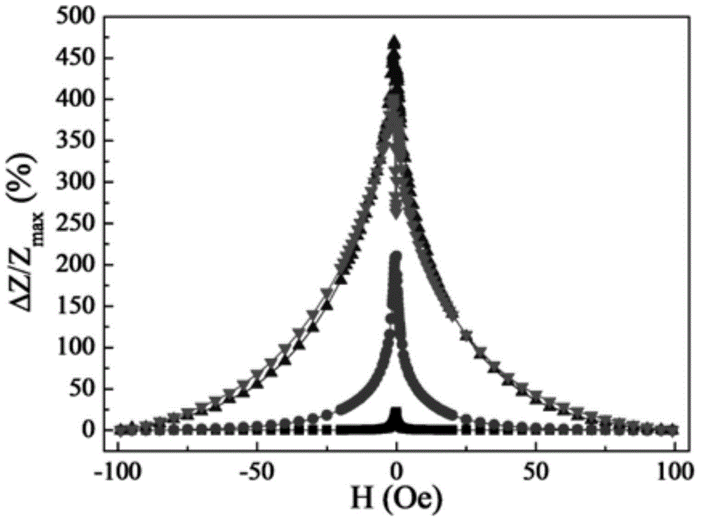
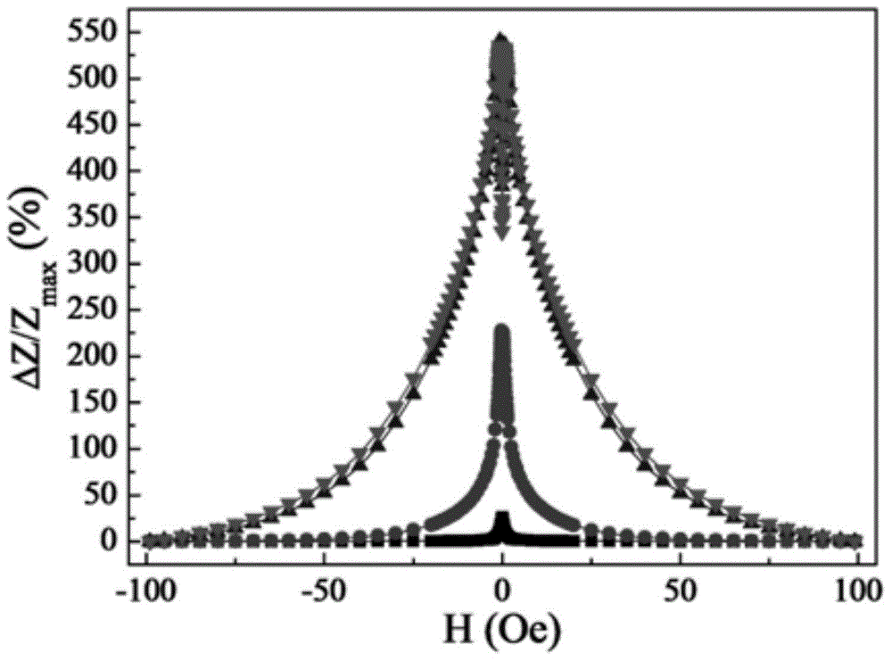
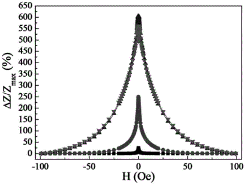
[0018] Specific embodiment one: a kind of amorphous microwire of this embodiment has the method for very high giant magneto-impedance effect to carry out according to the following steps:

[0019] 1. Select Co 68.15 Fe 4.35 Si 12.25 B 13.25 Nb 1 Cu 1 For amorphous microwires, the two ends of the microwires are fixed with copper flat-head fixtures, and placed in a zero-magnetic shielding space for impedance testing;

[0020] 2. After completing the impedance test of step 1, connect the microwire and the copper fixture into the circuit with a stable DC power supply, and perform the first step of step Joule annealing: the annealing current is 30-40mA, and the annealing time 8 to 10 minutes, after completion, connect it to the impedance test circuit for impedance test;

[0021] 3. After completing the first step of step two step Joule annealing, carry out the second step of step Joule annealing. The annealing current is 50-60mA, and the annealing time is 8-10min. After compl...

specific Embodiment approach 2

[0027] Embodiment 2: This embodiment is different from Embodiment 1 in that: in step 2, the annealing current is 40 mA, and the annealing time is 10 min. Others are the same as in the first embodiment.

specific Embodiment approach 3

[0028] Embodiment 3: This embodiment differs from Embodiment 1 or Embodiment 2 in that: in Step 3, the annealing current is 60 mA, and the annealing time is 10 min. Others are the same as in the first or second embodiment.


PUM


Abstract

The invention provides a method for generating super-high giant magneto impedance effect on an amorphous microwire, and relates to the method for generating the super-high giant magneto impedance effect. The method comprises the following steps: 1, fixing two ends of the microwire through copper flat head fixtures, and placing the microwire in a zero magnetic shielding room to conduct an impedance test; 2, conducting a first step of stepped joule annealing, and then connecting into an impedance test circuit to conduct the impedance test; 3, conducting a second step of the stepped joule annealing, and then connecting into the impedance test circuit to conduct the impedance test; 4, conducting a third step of the stepped joule annealing, and then connecting into the impedance test circuit to conduct the impedance test; 5, conducting a fourth step of the stepped joule annealing, and then connecting into the impedance test circuit to conduct the impedance test. Therefore, the method for generating the super-high giant magneto impedance effect on the amorphous microwire is realized. The method can be applied to the technical field of magnetic sensing and magnetic storing.

Description

technical field [0001] The invention relates to a method with a very high giant magneto-impedance effect. Background technique [0002] The giant magneto-impedance effect can be briefly described as: the phenomenon that the electrical impedance of the material changes dramatically due to the skin effect when an alternating current is applied to the material and a weak magnetic field is applied at the same time. (See Panina, L. and K. Mohri (1994). "Magneto-impedance effect in amorphous wires." Applied Physics Letters 65(9):1189-1191.). Based on this characteristic, the giant magneto-impedance (GMI) magnetic sensor has been developed. (See V. Zhukova, M. Ipatov, A. Zhukov. "Thin Magnetically Soft Wires for Magnetic Microsensors". Sensors. 2009, 9:9216-9240.). As a magnetically sensitive device, the material is required to have a good impedance change rate and high magnetic field sensitivity. Based on this, many studies have focused on improving the giant magnetoimpedance ef...

Claims


Application Information

Patent Timeline
IPC IPC(8): C22F1/10
Inventor 孙剑飞陈东明邢大伟
Owner HARBIN INST OF TECH
Learn More