Light curing device

A technology of light curing device and light pipe, which is applied in the field of light curing device, can solve the problems of poor mechanical properties and wear resistance, unreasonable setting position, poor curing of objects to be cured, etc., and achieve good curing effect and high work efficiency , Enhance the effect of light intensity and light range

Active Publication Date: 2018-01-05
SUZHOU LIREN HEARING EQUIP
View PDF5 Cites 0 Cited by
  • Summary
  • Abstract
  • Description
  • Claims
  • Application Information

AI Technical Summary

Problems solved by technology

[0003] The irradiation of ultraviolet light plays a vital role, but the location of the existing UV light tube that emits ultraviolet light is not reasonable enough, the curing of the cured product is poor, resulting in sticky surface of the cured product, poor mechanical properties and wear resistance , insufficient hardness and poor brightness
Therefore, in order to eliminate this bad defect when making ear molds and shells, it is necessary to add cleaning, polishing, varnish and other processes to remove the surface layer that is sticky, low in hardness, and poor in brightness, which is labor-intensive, time-consuming, and material-intensive. , energy consumption

Method used


Image

  • Light curing device
  • Light curing device
  • Light curing device

Examples


Embodiment 1

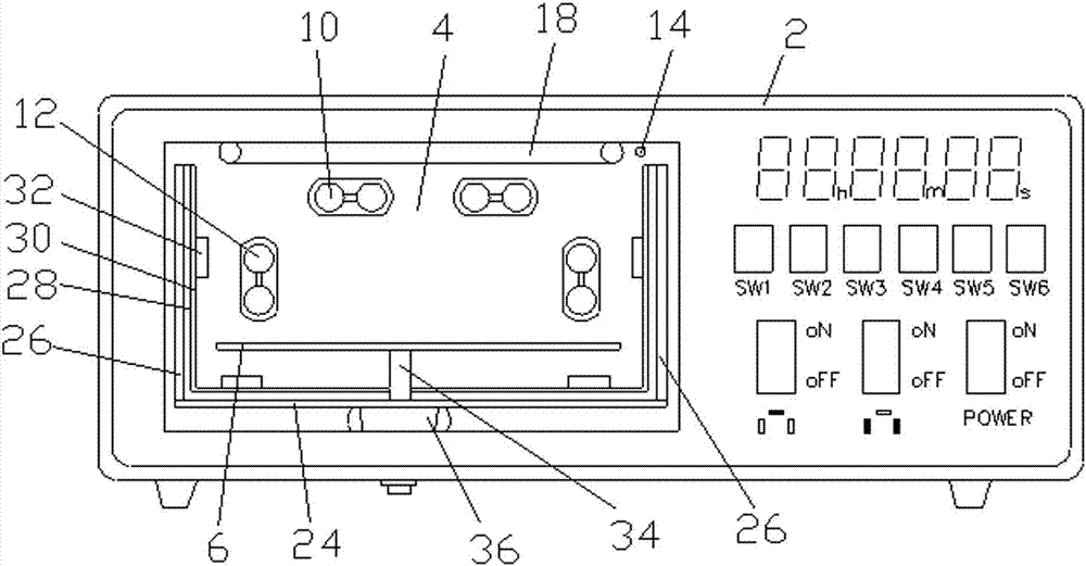
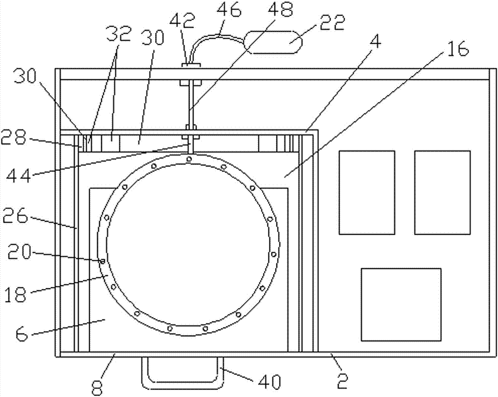
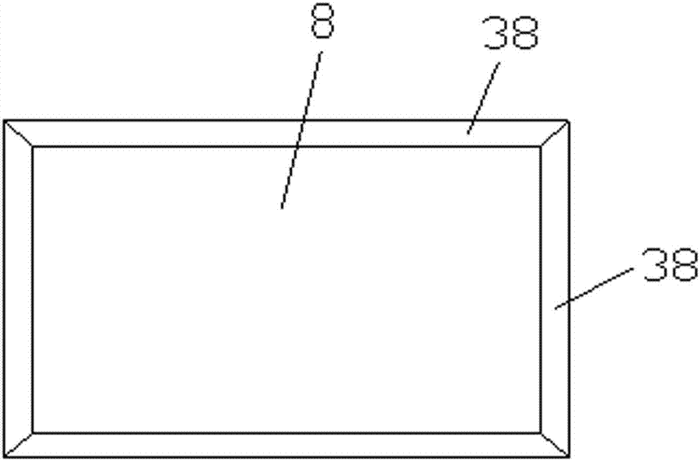
[0035] Such as figure 1 , figure 2 As shown, a photocuring device includes a casing 2 with an opening on the front side, a partition 4 inside the casing 2, and a movable shelf 6, on which the object to be cured is placed, and the opening is set There is an openable door panel 8, and the first row of UV light pipes and the second row of UV light pipes are arranged on the partition plate 4 above the shelf 6. The first row of UV light pipes includes two first UV light pipes 10, and the first row of UV light pipes 10. Two rows of UV light pipes include two second UV light pipes 12, the second UV light pipes 12 are lower than the first UV light pipes 10, the second UV light pipes 12 are located outside the first UV light pipes 10, and the first UV light pipes The arrangement of the tube 10 and the second UV light tube 12 has a strong light intensity and a wide light range, so that the curing effect of the object to be cured is good, and the product quality is improved.

[0036] ...

Embodiment 2

[0062] Such as Figure 6-Figure 10 As shown, the difference between the second embodiment and the first embodiment is that the two second UV light pipes 12 are arranged in a figure-eight structure, with strong illumination intensity and wide illumination range.

Embodiment 3

[0064] Such as Figure 11-Figure 14 As shown, a photocuring device includes a casing 2 with an opening on the front side, a partition 4 inside the casing 2, and a movable shelf 6, on which the object to be cured is placed, and the opening is set There is an openable door panel 8, and the first row of UV light pipes and the second row of UV light pipes are arranged on the partition plate 4 above the shelf 6. The first row of UV light pipes includes two first UV light pipes 10, and the first row of UV light pipes 10. Two rows of UV light pipes include two second UV light pipes 12, the second UV light pipe 12 is lower than the first UV light pipe 10, the second UV light pipe 12 is positioned at the outside of the first UV light pipe 10, and the shelf 6 There is a third row of UV light pipes below, the third row of UV light pipes includes two third UV light pipes 14, the arrangement of the first UV light pipe 10, the second UV light pipe 12 and the third UV light pipe 14 , the li...


PUM


Abstract

The invention relates to a light curing device, comprising a casing with an opening on the front side, a partition plate arranged in the casing, and a movable shelf, an openable door plate is arranged at the opening, and the partition plate is located at the side of the shelf. A first row of UV light pipes and a second row of UV light pipes are arranged above, the first row of UV light pipes includes at least two first UV light pipes, the second row of UV light pipes includes two second UV light pipes, and the second row of UV light pipes includes at least two first UV light pipes. The UV light pipe is lower than the first UV light pipe, and the second UV light pipe is located outside the first UV light pipe. The invention injects nitrogen gas into the curing chamber to drive away the oxygen in the curing chamber, so as to completely isolate the oxygen from contacting the ear mold or the outer shell. At the same time, the side plate or the inner tank is made of mirror stainless steel, which can enhance the light intensity of ultraviolet rays through reflection. , The arrangement of annular nitrogen injection pipe and multiple air injection holes accelerates the diffusion of nitrogen gas and at the same time makes the nitrogen gas distribution uniform. The special arrangement of the first UV light pipe, the second UV light pipe and the third UV light pipe makes the ear mold Or the shell is completely cured, and the curing effect is good.

Description

technical field [0001] The invention relates to a light curing device. Background technique [0002] Due to the different sizes and shapes of people's auricles, concha cavities, and ear canals, various ear molds and shells must be made during the process of wearing hearing aids to restore hearing. The base material used in the preparation of ear molds is a professional material. The professional material is to add a photoinitiator to a specially formulated resin, and the chemical reaction generated by high-intensity ultraviolet radiation splits into active free radicals or ions. These free radicals or ions The cross-linking reaction with the double bond in the prepolymer or unsaturated monomer forms a monomer gene to initiate polymerization, cross-linking and grafting reactions, and the resin is converted from liquid to solid in a few seconds to a few minutes. The application of light curing technology can greatly speed up the curing rate, reduce the amount of solvent disch...

Claims


Application Information

Patent Timeline
Patent Type & Authority Patents(China)
IPC IPC(8): B29C35/08
Inventor 徐斌吴秋麒
Owner SUZHOU LIREN HEARING EQUIP
Why Eureka
Try Eureka