
A combined traveling wave ranging method for high-voltage hybrid transmission lines

A transmission line and high-voltage hybrid technology, applied in the direction of the fault location, can solve problems such as complex ranging methods, waveform misjudgment, and affecting ranging accuracy, so as to improve accuracy and reliability, reduce the probability of misjudgment, and simplify The effect of combined traveling wave ranging method

Inactive Publication Date: 2017-10-31
SHANDONG UNIV OF TECH
View PDF7 Cites 0 Cited by
  • Summary
  • Abstract
  • Description
  • Claims
  • Application Information

AI Technical Summary

Problems solved by technology

[0007] This method eliminates the error of the synchronous clock and the error of the given length of the line, but this method needs to assume that the traveling wave surge that reaches the bus side for the second time is the reflection of the fault point or the reflection of the connection point between the cable and the overhead line after the section selection According to the hypothetical situation, after two ranging calculations, the time difference between the initial surge of the traveling wave and the arrival of the bus on both sides of the bus is calculated based on the obtained results, and then compared with the measured time difference to determine the ranging result. The ranging method is more complicated. It is easy to misjudge the waveform of the second arrival at the bus side, which affects the distance measurement accuracy

Method used


Image

  • A combined traveling wave ranging method for high-voltage hybrid transmission lines
  • A combined traveling wave ranging method for high-voltage hybrid transmission lines
  • A combined traveling wave ranging method for high-voltage hybrid transmission lines

Examples


Embodiment 1

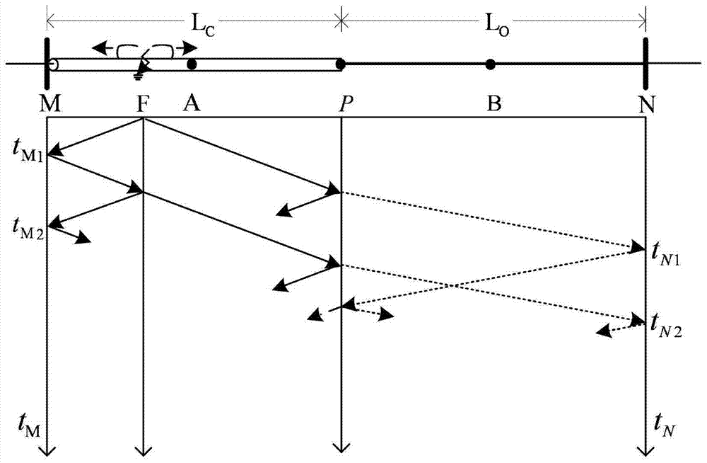
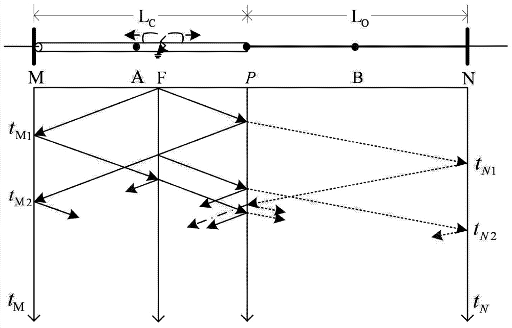
[0048] Cable MP segment length L C =18km, length L of overhead line NP section O =30km, A and B represent the midpoints of the cable transmission section and the overhead line transmission section respectively, and the propagation speed of the traveling wave in the cable is v C =192km / ms, the propagation speed of the traveling wave in the overhead line is v O =295km / ms, assuming that a fault occurs on the high-voltage hybrid transmission line at time t=0, the fault point F is located in the MA section of the cable, and the distance from it to the M end of the busbar is 4km.

[0049] calculate

[0050] Measured t M1 = 21μs, t M2 = 62.5μs, t N1 =175μs, get Δt=t M1 -t N1 =-154μs, obviously, Δt1 , it is determined that the fault point is located in the MA section of the cable and the waveform that reaches the M end of the bus for the second time is the reflected wave of the fault point.

[0051] According to the single-ended principle, the distance from the fault point F...

Embodiment 2

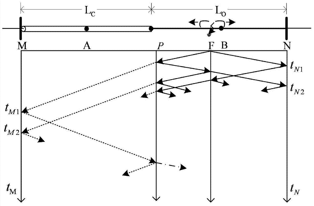
[0053] like image 3 As shown, the cable MP section length L C =18km, length L of overhead line NP section O =30km, A and B represent the midpoints of the cable transmission section and the overhead line transmission section respectively, and the propagation speed of the traveling wave in the cable is v C =192km / ms, the propagation speed of the traveling wave in the overhead line is v O =295km / ms, assuming that a fault occurs on the high-voltage hybrid transmission line at time t=0, the fault point F is located in the PB section of the overhead line, and the distance from it to the N terminal of the bus is 20km.

[0054] calculate

[0055] Measured t M1 = 128μs, t N1 = 68μs, t N2 =136μs, get Δt=t M1 -t N1 = 60μs, obviously, ΔT 2 3 , it is determined that the fault point is located in the PB section of the overhead line and the waveform that reaches the N end of the bus for the second time is the reflected wave of the connection point.


PUM


Abstract

A combined traveling wave ranging method for high-voltage hybrid transmission lines, which eliminates the influence of the double-terminal ranging principle due to the inaccurate synchronization of the time at both ends and the error of the given line length on the ranging accuracy, and improves the accuracy and accuracy of fault location. reliability. Including steps: 1), calculating the setting value: ΔT1, ΔT2, ΔT3; 2), collecting the time tM1 when the fault traveling wave reaches the cable bus side from the fault point for the first time and the time tM1 when the fault traveling wave reaches the overhead line from the fault point for the first time Time tN1 on the bus side, and calculate the time difference Δt = tM1‑tN1; 3) Take five points on the high-voltage hybrid transmission line: M, N, P, A, B; these five points combine the entire high-voltage hybrid transmission line The transmission line is divided into four sections; 4), judge the location of the fault point on the high-voltage hybrid transmission line and the waveform type that reaches the M terminal or N terminal for the second time: 5), calculate the distance from the fault point to the M terminal or N terminal.

Description

technical field [0001] The invention relates to the technical field of electric power system relay protection, in particular to a method for measuring distance with combined traveling waves of high-voltage hybrid transmission lines. Background technique [0002] With the rapid development of modern urbanization, available land resources are becoming increasingly scarce, and criss-crossing overhead lines occupy a large amount of available space, which is one of the main factors hindering urbanization. Therefore, gradually replacing overhead line network power supply with cable network power supply has become an inevitable trend of modern urbanization construction. Compared with overhead lines, cable lines have the advantages of high transmission capacity and reliability, low application cost, space saving, and beautification of the city. line hybrid line powered. However, due to factors such as the harsh operating environment of the cable and the imperfect manufacturing pro...

Claims


Application Information

Patent Timeline
IPC IPC(8): G01R31/08
Inventor 陈平梁凤强
Owner SHANDONG UNIV OF TECH
Learn More