Optical touch control display panel

A display panel and optical touch technology, applied to instruments, electrical digital data processing, data processing input/output process, etc., can solve problems such as misjudgment, uneven voltage, and insufficient reset voltage level of storage capacitors. Achieve the effects of improving uniformity, increasing voltage level, and reducing signal differences

Active Publication Date: 2013-06-12
AU OPTRONICS CORP
View PDF3 Cites 9 Cited by
  • Summary
  • Abstract
  • Description
  • Claims
  • Application Information

AI Technical Summary

Problems solved by technology

[0016] In view of the above problems, the present invention is to provide an optical touch display panel, so as to solve the problem of uneven voltage after reset of the storage capacitor on the same reset signal line in the prior art, and the difficulty in the reset voltage level of the storage capacitor. Problems that lead to misjudgment

Method used


Image

  • Optical touch control display panel
  • Optical touch control display panel
  • Optical touch control display panel

Examples


Embodiment Construction

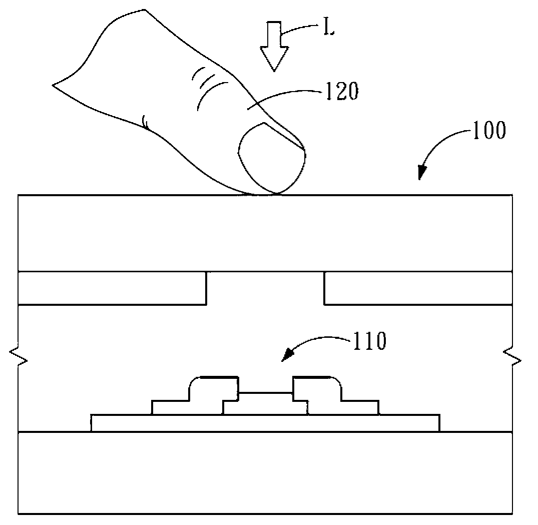
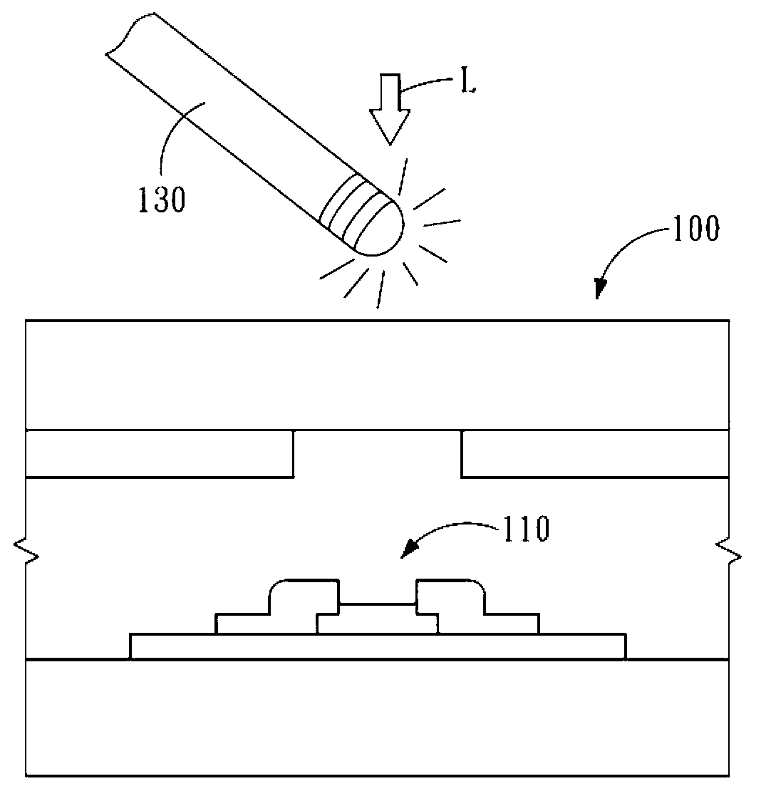
[0073] Figure 7 It is a schematic diagram of an optical touch display panel 200 according to an embodiment of the present invention.

[0074] like Figure 7 As shown, the optical touch display panel 200 includes a data driving circuit 210, a scanning driving circuit 220, a plurality of data signal lines Dm (that is, D1, D2, D3, ... Dm, m is a positive integer), a plurality of scanning signal lines Gn (i.e. G1, G2, G3, ... Gn, n is a positive integer), the reset drive circuit 250, a plurality of reset signal lines Sn connected to the reset drive circuit 250 (i.e. S1, S2, S3, ... Sn, n is a positive integer), a plurality of pixel regions 230 defined by the scanning signal line Gn and the data signal line Dm, a position detection circuit 240 and a plurality of reading signal lines Rj connected to the position detection circuit 240 (that is, R1, R2 , R3, ... Rj, j is a positive integer). These pixel regions 230 are arranged in matrix. The data driving circuit 210 is electrica...


PUM


Abstract

The invention provides an optical touch control display panel which comprises a plurality of reset signal lines, a plurality of scanning signal lines and a plurality of optical sensing touch control units. Each optical sensing touch control unit includes an optical sensing element and a storage capacitor. The optical sensing element includes a control end, an input end and a control end, and is used for outputting a sensing signal via an output end to the storage capacitor. The control ends of the optical sensing elements along a first direction are respectively connected to the different scanning signal lines and are used for receiving a control signal. The optical sensing elements along a second direction are divided into a plurality of groups, wherein the input ends of the optical sensing elements of each group are respectively connected to the different reset signal lines so that a reset signal is received by each group. Each optical sensing element outputs, based on the control signal, a charging signal corresponding to the reset signal to the storage capacitor so that voltages of the storage capacitor is reset.

Description

technical field [0001] The present invention relates to a touch display panel, in particular to an optical touch display panel. Background technique [0002] With the development of science and technology, many consumer electronic products (such as personal digital assistants (PDA), mobile phones, tablet computers, etc.) have widely used touch display panels as communication interfaces for human-machine data. The touch display panel can use different sensing technologies such as resistive, capacitive, and photosensitive to detect the position touched by the user on the touch display panel. [0003] figure 1 It is a schematic diagram of detection of the photosensitive touch display panel 100 . figure 2 It is another detection schematic diagram of the photosensitive touch display panel 100 . image 3 It is a schematic diagram of the light sensing signal generated by the light sensing element 110 receiving different light intensities. [0004] Such as figure 1 As shown, t...

Claims


Application Information

Patent Timeline
Patent Type & Authority Applications(China)
IPC IPC(8): G06F3/042
CPCG06F3/042G06F3/0412
Inventor 陈汉铭钟岳宏徐雅玲黄雪瑛
Owner AU OPTRONICS CORP
Why Eureka
Try Eureka