
Heat storage burning system

A heat supply system and heat storage technology, applied in the direction of incinerators, combustion methods, combustion types, etc., can solve problems such as prone to danger, inability to lengthen air ducts, and slow feedback speed of concentration detectors, so as to reduce pollution and ensure equipment safety Reliable, easy-to-maintain results

Inactive Publication Date: 2015-04-22
江苏百茂源环保科技有限公司
View PDF11 Cites 5 Cited by
  • Summary
  • Abstract
  • Description
  • Claims
  • Application Information

AI Technical Summary

Problems solved by technology

The regenerative oxidation furnace consists of a furnace and two or more heat storage beds. Taking two heat storage beds as an example, the two heat storage beds will periodically absorb and release heat, and the organic waste gas passes through the heat storage beds. After entering the furnace for combustion and decomposition, since the organic waste gas is a flammable and explosive gas, if the concentration is too high and exceeds the lower limit of explosion, it will easily cause danger, so the concentration of organic waste gas entering the regenerative oxidation furnace must be controlled, and the concentration detector The parameter feedback speed is relatively slow, and this situation is generally solved by lengthening the air duct to prolong the time for the exhaust gas to enter the regenerative oxidation furnace, but some conditions are limited, such as insufficient site area, etc., the air duct cannot be lengthened, which belongs to a long-standing technology problem

Method used


Image

  • Heat storage burning system
  • Heat storage burning system

Examples


Embodiment 1

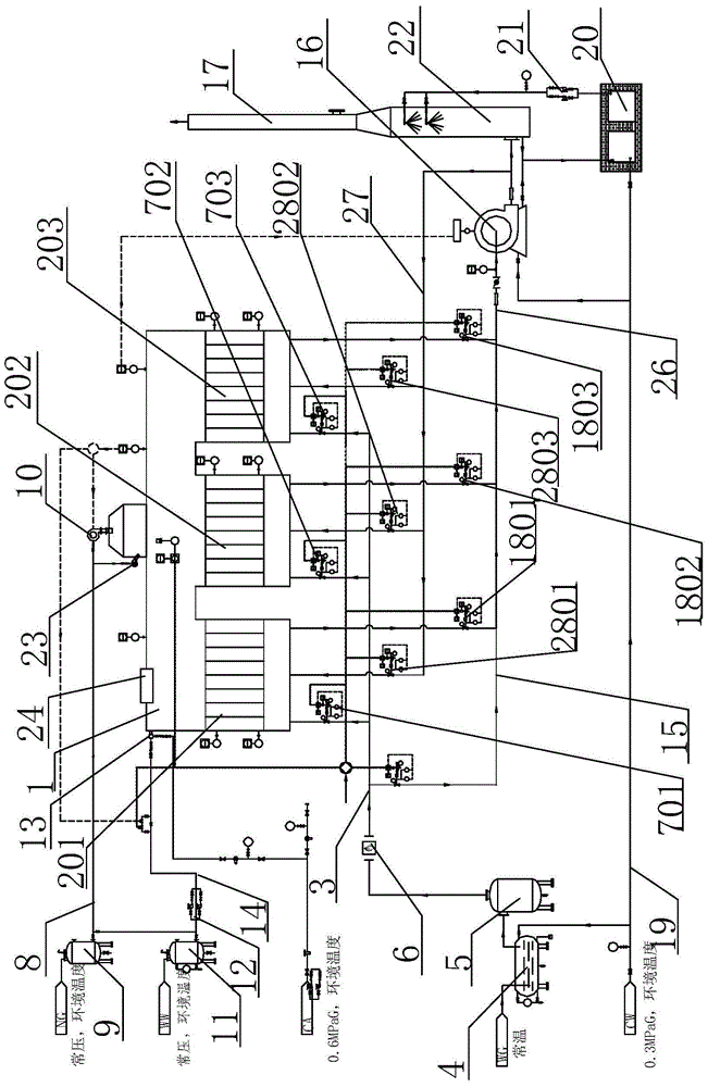
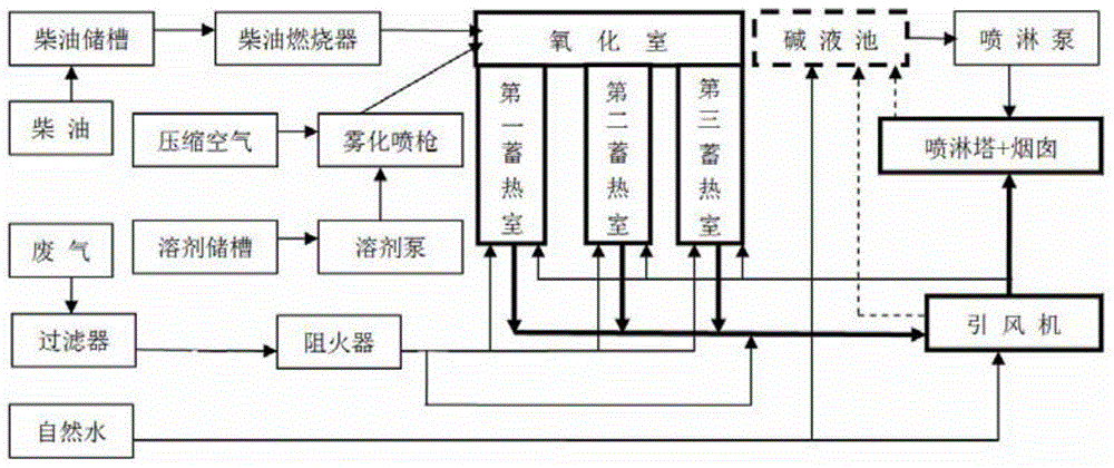
[0028] The thermal storage incineration system provided by this embodiment has a structure such as figure 1 with 2 Shown, including heating system, combustion-supporting solvent system, thermal storage oxidation system, air intake system, exhaust system and flue gas spray system, air intake system, combustion-supporting solvent system and air intake system are connected in series with the thermal storage oxidation system. The inlet is connected in parallel with the intake system, combustion-supporting solvent system and the intake system. The outlet of the thermal storage oxidation system is connected in series with the exhaust system, and the exhaust system is connected to the flue gas spray system. Among them:

[0029] The heat storage oxidation system includes a heat storage chamber 2 and an oxidation chamber 1. The oxidation chamber 1 is also equipped with a permanent flame burner 23 and a flame detector. The top of the oxidation chamber 1 is equipped with an explosion-proof op...


PUM


Abstract

The invention discloses a heat storage burning system. The system comprises a heat supply system, a combustion supporting solvent system, a heat storage oxidization system, a gas inlet system, an exhaust system and a smoke spraying system, wherein the heat supply system, the combustion supporting solvent system and the gas inlet system are connected to an inlet of the heat storage oxidization system in series, the exhaust system is connected to an outlet of the heat storage oxidization system in series and connected with the smoke spraying system, a diesel combined heat supply system preheats a heat storage chamber in the heat storage oxidization system, waste gas enters the heat storage chamber through the gas inlet system to be heated and then enters an oxidization chamber in the heat storage oxidization system to be subjected to oxygenolysis, and smoke passes through the exhaust system and is exhausted to the atmosphere after acid gas in the smoke is removed through the smoke spraying system. According to the heat storage burning system, the waste gas is subjected to heat storage oxidization through automatic alternate switching, time is saved, efficiency is improved, heat emission generated after waste gas treatment is reduced, high heat efficiency is achieved, VOCs in the waste gas is high in decomposition rate, and the system is safe and reliable, easy to operate and low in running cost in use.

Description

technical field [0001] The invention relates to a device for treating organic waste gas, in particular to a thermal storage incineration system for treating organic waste gas. Background technique [0002] Air pollution is one of the most prominent environmental problems in my country at present. Industrial waste gas is an important source of air pollutants; a large amount of industrial waste gas is discharged into the atmosphere, which will inevitably reduce the quality of the atmospheric environment, bring serious harm to human health, and cause huge economic losses to the national economy. loss. The most difficult thing to deal with in industrial waste gas is organic waste gas. After organic waste gas enters the human body through the respiratory tract and skin, it can cause temporary and permanent lesions to human respiratory, blood, liver and other systems and organs, especially benzopyrene polycyclic Aromatic hydrocarbons can directly cause cancer in the human body, wh...

Claims


Application Information

Patent Timeline
IPC IPC(8): F23G7/06
CPCF23G7/06
Inventor 吴军伟谈立刚王琴丁乾
Owner 江苏百茂源环保科技有限公司
Learn More