
Gravity rotated casting pouring basin

A sprue basin and gravity technology, which is applied to casting molding equipment, molds, mold components, etc., can solve the problems of lowering the qualified rate of products, flowing into the cavity, and failing to make smooth transitions, reducing slag hole defects, improving Flow characteristics, the effect of reducing oxidation slag inclusion

Active Publication Date: 2015-04-22
XIAN AERO ENGINE CONTROLS
View PDF18 Cites 7 Cited by
  • Summary
  • Abstract
  • Description
  • Claims
  • Application Information

AI Technical Summary

Problems solved by technology

This type of sprue cup has good thermal insulation, but the junction between the sprue cup and the mold cannot be smoothly transitioned, and the molten metal flow is not stable enough when it enters the cavity, and it is easy to splash and generate oxidized slag inclusions, forming oxidized slag inclusion defects in castings. Greatly reduced the pass rate of the product
[0004] The second sprue cup type, such as the cross-section controllable sprue cup proposed by Wenzhou Ruiming Co., Ltd., has an application number of 201210443819.6. The wall thickness of this cast iron sprue cup is about 15mm, and its heat storage capacity is good. The gate section of the molten metal entering the cavity is fixed, but the sprue cup filter is not easy to fix, and some oxidized inclusions are easy to flow into the cavity from the side of the filter during the tilting process, resulting in slag inclusion defects in the product and reducing Product pass rate
In addition, the baffle plate of the control section on the sprue cup is fixed and cannot be adjusted according to the needs of the process. At the same time, the oxidized inclusions remaining near the gate of the sprue cup after pouring are difficult to clean
In addition, the baffle is made of steel, and the contact between the baffle and the molten aluminum will easily increase the iron content of the molten metal, resulting in unqualified chemical composition of the product.

Method used


Image

  • Gravity rotated casting pouring basin
  • Gravity rotated casting pouring basin
  • Gravity rotated casting pouring basin

Examples


Embodiment Construction

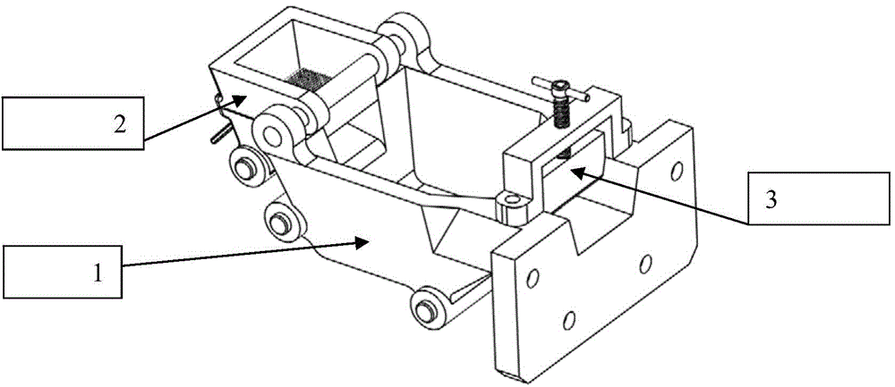
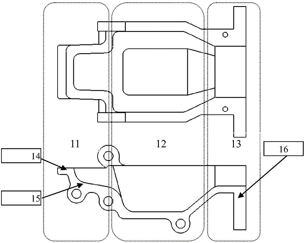
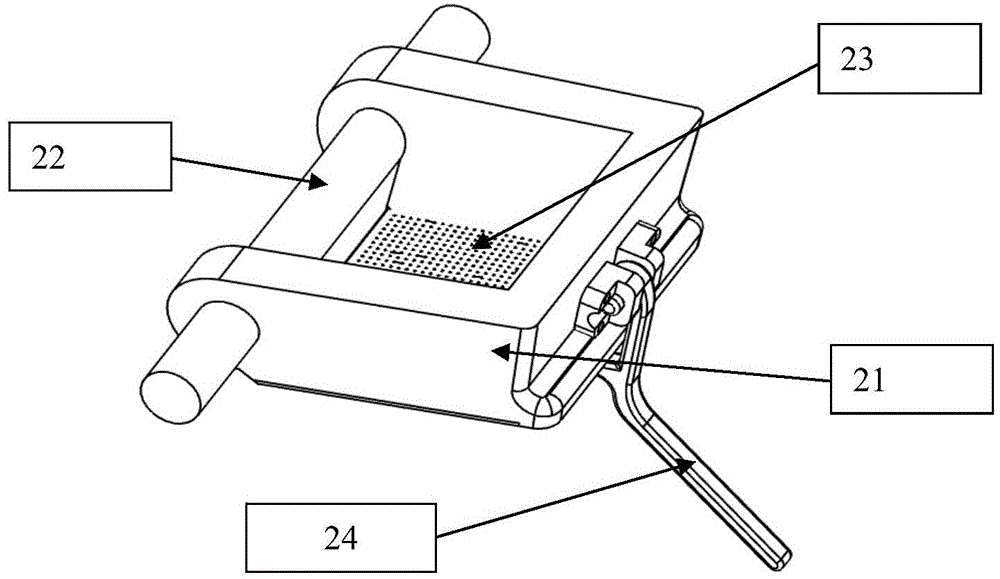
[0024] see figure 1 as well as figure 2 , the present invention provides a gravity tilt casting sprue pot, comprising a sprue pot body 1, the sprue pot body 1 includes a body bottom and a side wall extending outward along the edge of the body bottom; the sprue pot body 1 along The direction in which the pouring liquid flows is divided into a liquid inlet area 11, a liquid holding area 12, and an inlet gate 13; among them, the liquid inlet area 11 is used to buffer and filter the molten metal transferred into the sprue basin in the ladle, and the liquid holding area 12 is used to accommodate the molten metal flowing in from the liquid inlet area 11, and the gate is smoothly connected with the mold runner for pouring during the tilting process; the bottom of the body is correspondingly divided into the bottom of the liquid inlet area, the bottom of the liquid holding area and the inlet The bottom of the gate; the bottom of the liquid inlet area is the impact slope 15, and the ...


PUM


Abstract

The invention relates to a gravity rotated casting pouring basin, which comprises a pouring basin body, the pouring basin body comprises a bottom and a side wall outwardly extended along the edge of the bottom; the pouring basin body is divided into a liquid inlet zone, a liquid filling zone and a casting gate in order along the cast liquid flow; the bottom is divided into a liquid inlet zone bottom, a liquid filling zone bottom and a casting gate bottom which are smoothly connected; and the liquid inlet zone bottom is an impact inclined plane. The gravity rotated casting pouring basin is capable of improving the flow characteristic of molten metal in the pouring basin and realizing the stable state casting of the molten metal.

Description

technical field [0001] The invention belongs to the technical field of casting mold structure design, and relates to a gravity tilting casting sprue basin. Background technique [0002] There are generally two types of sprue basins for gravity tilt casting: [0003] The first one is the gravity tilting pouring machine thermal insulation sprue cup proposed by Harbin Dongan Automobile Co., Ltd., and its patent number is 201220755199.5. The sprue cup is made of thin steel double-layer steel plates welded into the sprue cup, and the hollow layer is filled with thermal insulation materials. This type of sprue cup has good thermal insulation, but the junction between the sprue cup and the mold cannot be smoothly transitioned, and the molten metal flow is not stable enough when it enters the cavity, and it is easy to splash and generate oxidized slag inclusions, forming oxidized slag inclusion defects in castings. Greatly reduced the pass rate of the product. [0004] The second...

Claims


Application Information

Patent Timeline
IPC IPC(8): B22C9/08
CPCB22C9/082
Inventor 冯超茄菊红唐桢王嘉辉余腾飞王勇
Owner XIAN AERO ENGINE CONTROLS
Learn More