
Pneumatic flour transmitting system

A conveying system and negative pressure pneumatic conveying technology, which is applied in the field of pneumatic conveying system and flour pneumatic conveying system, can solve the problems such as the large influence of mixing effect, and achieve the effect of low operating cost, simple conveying system and large conveying capacity

Inactive Publication Date: 2015-04-15
NINGXIA JIAXIANG AUTOMATIC CONTROL TECH
View PDF6 Cites 14 Cited by
  • Summary
  • Abstract
  • Description
  • Claims
  • Application Information

AI Technical Summary

Problems solved by technology

But its mixing effect is greatly affected by the sealing effect

Method used


Image

  • Pneumatic flour transmitting system

Examples


Embodiment 1

[0009] Embodiment 1 Composition and function of a pneumatic conveying system for flour:

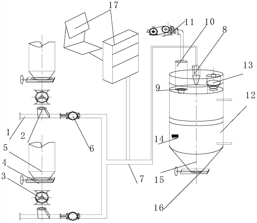
[0010] The conveying system includes flour and air flow pipeline Ⅰ1, gas-solid mixing acceleration chamber 2, electric discharge valve 3, electric flapper valve 4, hopper 5, pneumatic reversing valve 6, flour and air flow pipeline Ⅱ7, cyclone dust collector 8, closing Fan 9, pulse back blowing bag filter 10, Roots blower 11, silo 12, pressure release valve 13, vibrating air hammer 14, activation hopper 15, pneumatic flapper valve 16, electrical control system 17, characterized in Roots blower 10 uses negative pressure to suck and convey dilute phase flour. It is suitable for conveying systems with short distance, large conveying capacity and continuous conveying requirements. It is a flour pneumatic conveying system that can convey flour from multiple points to one point. The gas-solid mixing chamber 2 is used for mixing flour and air flow, so that the flour has acceleration. The elect...

Embodiment 2

[0011] Embodiment 2 The working process of a pneumatic conveying system for flour:

[0012] After the flour is added from the hopper 5, it enters the gas-solid mixing acceleration chamber 2 through the electric discharge valve 3. At this time, the branch flour and one end of the air flow pipe I are open to the atmosphere, and the air flow is sucked into the pipe under the action of the Roots blower 11. , mixed with flour in the gas-solid mixing acceleration chamber 2, controlled by the pneumatic switching valve 6 according to the process and production needs, entering the flour and air flow pipeline II 7, entering the cyclone dust collector 8 and feeding into the silo 12, and passing through the pneumatic inserting plate The outlet of valve 16 is discharged.


PUM


Abstract

The invention relates to a pneumatic flour transmitting system which is especially suitable for a negative-pressure pneumatic conveying system for flour. The pneumatic flour transmitting system comprises a flour and gas flow pipeline II, a gas-solid mixing accelerating room 2, an electronic unloading valve 3, a manual insertion plate valve 4, a hopper 5, a pneumatic reversing valve 6, a flour and gas flow conveying pipeline II 7, a cyclone dust collector 8, an air sealing machine 9, a pulse reverse-blowing bag type filter 10, a Roots blower 11, a material bin 12, a pressure release valve 13, a vibrating gas hammer 14, an activating hopper 15, a pneumatic insertion plate valve 16 and an electrical control system 17. The pneumatic flour transmitting system is characterized in that the Roots blower 11 is used for absorbing and transmitting rear-phase flour through negative pressure. The pneumatic flour transmitting system has the beneficial effects of relatively great system transmitting amount, and a simple transmitting system; the Roots blower is used for absorbing and transmitting through negative pressure, so that the maintenance rate and the fault rate are low, and the operation cost is low.

Description

technical field [0001] The invention relates to a pneumatic conveying system for flour, especially suitable for a short-distance flour conveying system with a large conveying capacity, continuous conveying requirements, and a flour conveying system that can convey flour from multiple points to one point, and belongs to the pneumatic conveying technology field. Background technique [0002] At present, the conveying of flour in the field of pneumatic conveying adopts the negative pressure dilute phase conveying method. Among them, the flour conveying valve is also called E-shaped valve. The conveying valve as the receiver is one of the key equipment of the negative pressure system. Its function is to make the ash hopper The ash and air inside are evenly mixed, and the ash-air mixture has good fluidity, which can make it enter the conveying pipeline smoothly, so as to ensure the efficient and smooth operation of the conveying system. However, its mixing effect is greatly aff...

Claims


Application Information

Patent Timeline
IPC IPC(8): B65G53/24B65G53/34B65G53/40B65G53/36B65G53/66
Inventor 李黎
Owner NINGXIA JIAXIANG AUTOMATIC CONTROL TECH
Learn More