
High frequency sewing machine

A sewing machine and high-frequency technology, which is applied in the field of high-frequency sewing machines, can solve the problems of poor quality of finished clothing products, scorched or scalded fiber fabrics, and wrinkled fiber fabrics, etc., to achieve a good visual effect and appearance, and to prevent scorching , to avoid wrinkling effect

Inactive Publication Date: 2015-04-15
YAMATO SEWING MASCH MFG CO LTD
View PDF5 Cites 6 Cited by
  • Summary
  • Abstract
  • Description
  • Claims
  • Application Information

AI Technical Summary

Problems solved by technology

[0008] However, in the high-frequency sewing machine disclosed in Japanese Patent Application Laid-Open No. 2014-058148, a pair of upper and lower electrodes are arranged relative to each other with a certain distance between the material to be processed. Therefore, parts other than the electrodes, such as wires and The parts adjacent to the electrode will generate heat with the application of high-frequency electricity, and the heat will spread and affect the surroundings, which will easily cause disadvantages such as scorching or scalding of the fiber fabric
[0009] In addition, in the high-frequency sewing machine disclosed in JP-A-2014-058148, a pair of upper and lower rollers arranged so as to sandwich the workpiece from both sides of the workpiece are used as the conveyance tool for the workpiece. The roller device, through the relative rotation of the upper and lower pair of rollers of the roller device, continuously and forcibly conveys the processed material at a constant speed along the processing direction. Therefore, in order to make the adhesive of the high-frequency electric fusion thermoplastic resin In the fiber fabric, the pressing force of the roller is required to be large, but in this case, the strong pressing force generated by the roller tends to wrinkle the fiber fabric of the processed material, and as a result, there will be a new problem of poor quality of the finished apparel product. question

Method used


Image

  • High frequency sewing machine
  • High frequency sewing machine
  • High frequency sewing machine

Examples


Embodiment Construction

[0054] Embodiments of the present invention will be described below with reference to the drawings.

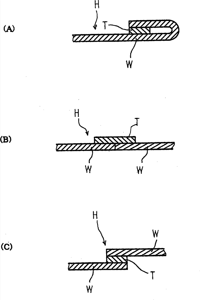
[0055] figure 1 It is a perspective view of the overall appearance of the high-frequency sewing machine according to the embodiment of the present invention, figure 2 It is a left side view showing a part of the whole high-frequency sewing machine, image 3 It is an enlarged cross-sectional view of the main part of the processed material as the processing object of this high-frequency sewing machine, Figure 4 An enlarged longitudinal sectional front view of main parts for explaining the main part structure of the high-frequency sewing machine, Figure 5 It is an enlarged longitudinal sectional side view of main parts for explaining the structure of main parts of this high-frequency sewing machine.

[0056] Such as figure 1 and figure 2 As shown, a high-frequency sewing machine 1 is composed of a sewing machine main body 2 , a sewing machine arm 3 and a sewing machine b...


PUM


Abstract

A high frequency sewing machine includes a pair of endless belts arranged at upper and lower sides; a pair of rollers arranged at upper and lower sides; an upper electrode having a function of pressing a machined material and a lower electrode opposite to the upper electrode; a high frequency power applying device; a control unit; and a roller lifting mechanism and an electrode lifting mechanism which can perform switching control between a first bonding action mode and a second bonding action mode, in the first bonding action mode, the upper roller and the upper electrode are descended to continuously convey a machined material while high frequency power is continuously applied between the upper and lower electrodes, in the second bonding action mode, the upper roller depart towards the upper side, and at the same time, the upper electrode intermittently rises and falls to convey the machined material while the high frequency power is intermittently applied between the upper and lower electrodes. The high frequency sewing machine can prevent the occurrence of indentations and overheated traces, burning, burnout, and the wavy shape of a fabric, and can also easily and surely bond curvilinear portions.

Description

technical field [0001] The present invention relates to fabrics made of natural fibers represented by cotton, wool, silk, etc., or synthetic fibers represented by polyester, nylon, acrylic, etc. (hereinafter referred to as "fiber fabrics" in the present invention) A high-frequency sewing machine used to process and manufacture clothing (clothes) such as women's wear, children's wear, and men's wear by bonding (welding) the ends of such fiber fabrics with a thermoplastic resin tape melted by high-frequency induction heating. Background technique [0002] A high-frequency sewing machine that uses high-frequency electricity and a thermoplastic resin belt to bond two pieces of fiber fabrics to make apparel products only needs to have: a conveying device that is used to transport (transfer) the fiber fabric and thermoplastic resin along the horizontal plane in a specific direction. a material to be processed constituted by a belt; high-frequency electricity applying means for app...

Claims


Application Information

Patent Timeline
IPC IPC(8): B29C65/04
CPCB29C65/04B29C65/4815B29C65/5042B29C65/5057B29C65/7894B29C66/003B29C66/006B29C66/1122B29C66/1142B29C66/135B29C66/244B29C66/43B29C66/71B29C66/729B29C66/8161B29C66/8242B29C66/83423B29C66/836B29C66/845B29C66/87443B29C66/91651B29C66/92615B29C66/93451B29K2055/02B29K2059/00B29K2069/00B29K2071/00B29K2077/00A41H43/04B29C65/78
Inventor 植山裕之宫井沙希
Owner YAMATO SEWING MASCH MFG CO LTD
Learn More