
Gas sampling and detecting device

A detection device and gas sampling technology, applied in the direction of measuring devices, sampling devices, instruments, etc., can solve problems such as dust blockage, atmospheric environment interference, etc., achieve the effects of reducing pollution and blockage, increasing purging equipment, and optimizing dust removal effect

Inactive Publication Date: 2015-04-08
GL TECH CO LTD
View PDF7 Cites 14 Cited by
  • Summary
  • Abstract
  • Description
  • Claims
  • Application Information

AI Technical Summary

Problems solved by technology

[0009] The purpose of the present invention is to provide a gas sampling device to solve the problem that the prior art cannot fundamentally solve the problem of dust clogging, or the problem of introducing interference from the external atmospheric environment

Method used


Image

  • Gas sampling and detecting device
  • Gas sampling and detecting device
  • Gas sampling and detecting device

Examples


Embodiment 1

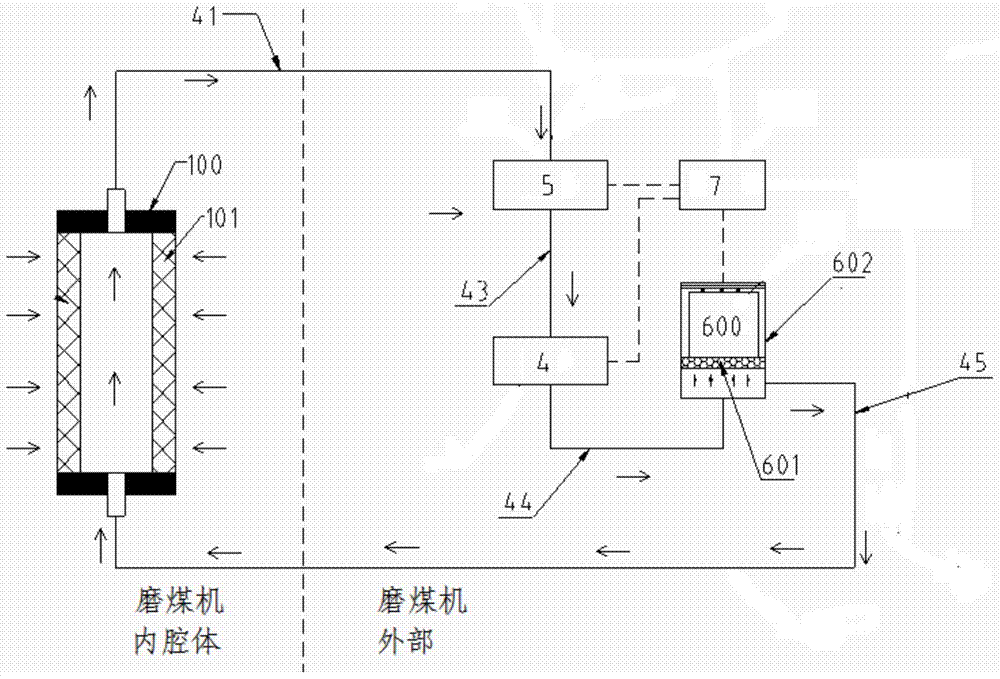
[0032] Such as figure 1 The gas sampling and detection device shown is used for carbon monoxide sampling of coal mills. It includes a closed circulation air path, in which a collecting and filtering device 100 and a sampling main body are arranged in series. The collecting and filtering device 100 has an internal cavity communicated with the closed circulation air path, and a filter channel 101 for communicating the internal cavity with the external dust environment. The sampling main part includes an air pump 4 and a gas detection device for driving the gas flow in the closed loop air circuit.

[0033] The filter channel 101 is a filter arranged around the inner cavity of the collection filter device 100 , and the main purpose of the present invention is to reduce the pollution and blockage of the filter by dust.

[0034] The air pump 4 adopts a vacuum air pump, such as an explosion-proof vacuum air pump.

[0035] The collection and filtration device 100 is installed on th...

Embodiment 2

[0044]Although the solution in Example 1 fundamentally reduces the clogging of the filter by coal dust, when it is placed in a coal dust environment for a long time, coal dust is still easy to adhere to the filter.

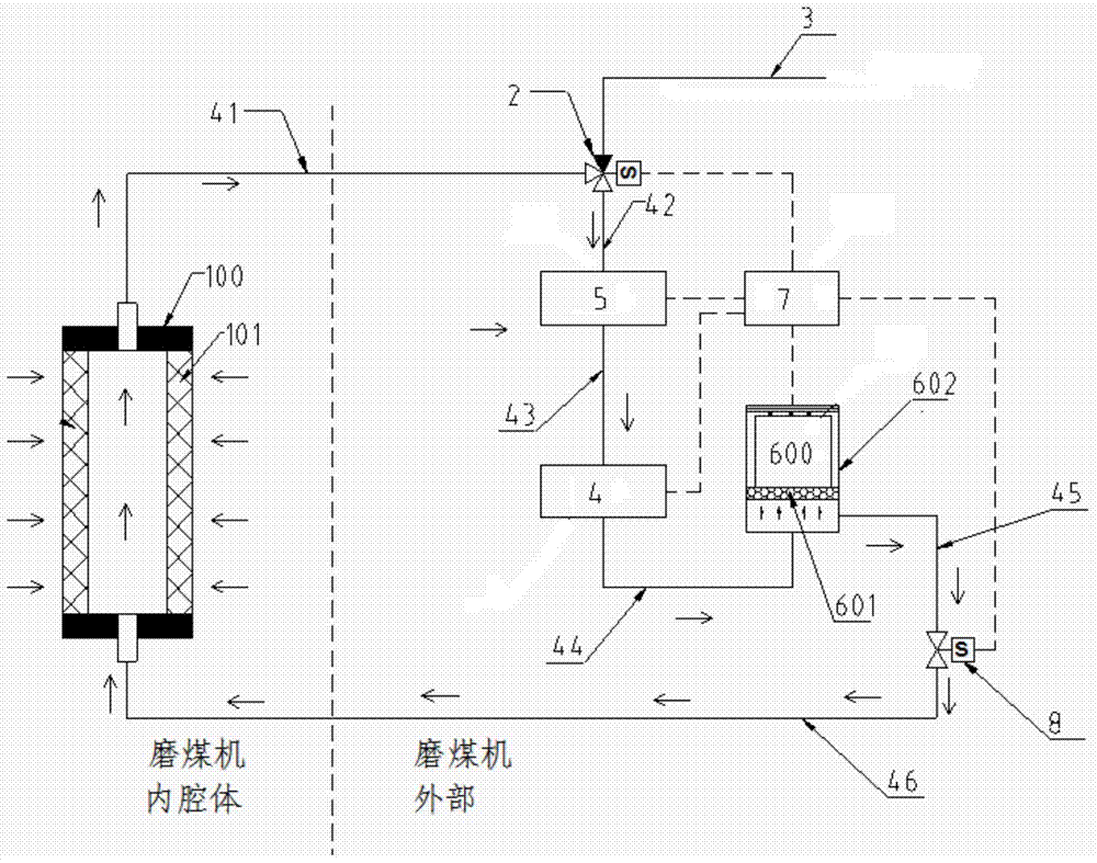
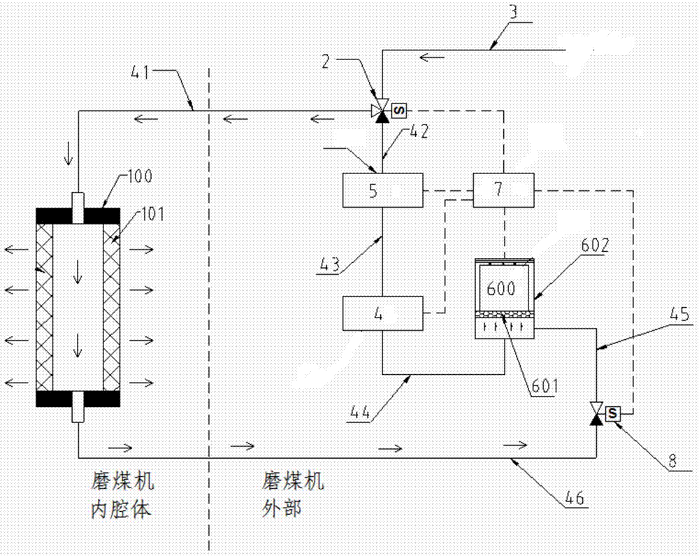
[0045] Such as figure 2 , image 3 It is an embodiment to increase the purging function to remove the attached coal dust by purging. In this way, the closed loop gas path has two working states, one is the sampling detection state, and the other is the purging state.

[0046] The system is implemented as follows:

[0047] A purge control valve 2 and a blocking valve 8 are set in the closed cycle gas circuit. The purge control valve is a three-way valve, the three-way valve has first, second and third gas ports, the first gas port is the purge gas inlet, connected to the compressed air 3; The air passage section 41 communicates with the internal cavity of the collection and filtration device 100 , and the third air port communicates with the sampling main body...


PUM


Abstract

The invention relates to a gas sampling and detecting device. The gas sampling and detecting device comprises a closed circulation gas circuit, wherein a collecting and filtering device (100) and a sampling main body are connected in series in the closed circulation gas circuit; the collecting and filtering device (100) is provided with an inner cavity and a filtering channel, the inner cavity is communicated with the closed circulation gas circuit, and the filtering channel (101) is used for communicating the inner cavity with the outside dust environment; and the sampling main body comprises a gas pump and a gas detecting device, and the gas pump is used for driving gas in the closed circulation gas circuit to flow. According to the closed-circuit self-circulation gas sampling principle, the sampled gas is made to circulate in a relatively closed environment, and the gas in the dust environment is not pumped directly by the gas pump, thus the filter pollution and blockage caused by dust can be reduced fundamentally. More importantly, the closed gas circuit can not be disturbed by the outside environment, and a filtering device for filtering the disturbance of the outside environment does not need to be arranged additionally.

Description

technical field [0001] The invention relates to a gas sampling device suitable for high dust concentration, which belongs to the field of gas collection and detection. Background technique [0002] At present, the carbon monoxide monitoring of domestic coal mills basically adopts the method of sampling and analysis. The sampling gas containing a large amount of coal dust and coal powder particles enters the sampling pipeline, and the particulate state coal powder and coal dust in the sampling gas are removed through several stages of filtration. It then enters the sensor chamber for analysis and then empties. Although these monitoring technologies have played an important role in the monitoring of carbon monoxide concentration in coal mills, they also have various shortcomings: [0003] 1. Sampling is carried out by extracting gas from the chamber of the coal mill. Coal dust and coal powder are easy to block the filter device, resulting in inaccurate measurement. [0004] ...

Claims


Application Information

Patent Timeline
Patent Type & Authority Applications(China)
IPC IPC(8): G01N1/24G01N33/00
Inventor 赵彤宇高华石云鹏朱海龙周正
Owner GL TECH CO LTD
Learn More