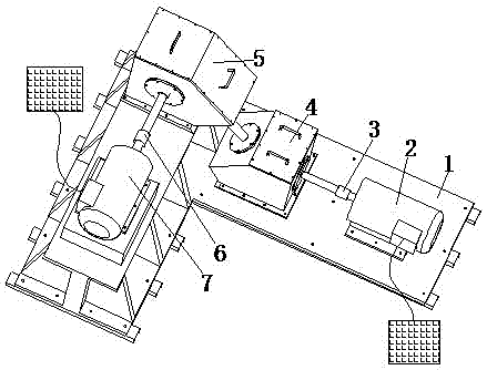
A fault simulation experiment device for helicopter tail drive system
A tail drive system and fault simulation technology, applied in the field of helicopter tail drive system fault simulation experiment device, can solve the problems of strong, broken parts and vibration, etc.
- Summary
- Abstract
- Description
- Claims
- Application Information
AI Technical Summary
Problems solved by technology
Method used
Image

Examples
Embodiment 1
[0051] Example 1 Simulation of pitting faults in the inner ring of a double row tapered roller bearing.
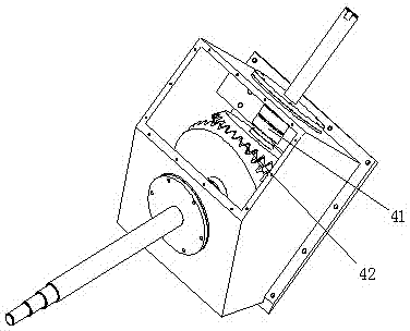
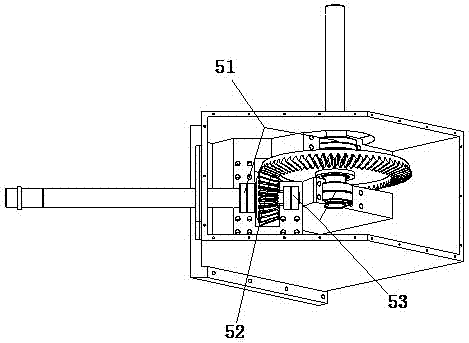
[0052] Replace the double-row tapered roller bearing 41 supporting the driving wheel of the first reducer with a faulty bearing with pitting faults in the inner ring, start the drive motor 2, set the input speed to 1800r / min, and connect the sensor output line to the B&K data acquisition system. After the B&K data acquisition system converts the analog signal into a digital signal, the data is transmitted to the computer data acquisition software through the network cable, and the vibration acceleration time series signal is obtained. The time domain signal diagram is as follows Figure 6 .
Embodiment 2
[0053] Example 2 Simulation of Pitting Corrosion Faults in the Outer Ring of Double Row Tapered Roller Bearings
[0054] Replace the double-row tapered roller bearing 41 supporting the driving wheel of the first reducer with a faulty bearing with pitting faults on the outer ring, start the drive motor 2, set the input speed to 1800r / min, and connect the sensor output line to the B&K data acquisition system. After the B&K data acquisition system converts the analog signal into a digital signal, the data is transmitted to the computer data acquisition software through the network cable, and the vibration acceleration time series signal is obtained. The time domain signal diagram is as follows Figure 7 .
Embodiment 3
[0055] Example 3 Simulation of Roller Pitting Corrosion Fault of Double Row Tapered Roller Bearing
[0056] Replace the double-row tapered roller bearing 41 supported by the driving wheel of the first reducer 4 with a faulty bearing with roller pitting faults, start the drive motor 2, set the input speed to 1800r / min, and connect the sensor output line to the B&K data acquisition system, the B&K data acquisition system converts the analog signal into a digital signal, and then transmits the data to the computer data acquisition software through the network cable to obtain the vibration acceleration time series signal. The time domain signal diagram is as follows Figure 8 .
PUM
 Abstract
Description
Claims
Application Information
 - R&D
- Intellectual Property
- Life Sciences
- Materials
- Tech Scout
- Unparalleled Data Quality
- Higher Quality Content
- 60% Fewer Hallucinations
Browse by: Latest US Patents, China's latest patents, Technical Efficacy Thesaurus, Application Domain, Technology Topic, Popular Technical Reports.
© 2025 PatSnap. All rights reserved.Legal|Privacy policy|Modern Slavery Act Transparency Statement|Sitemap|About US| Contact US: help@patsnap.com