Online machining detection device and method for directional sleeve of overrun clutch
An overrunning clutch and detection device technology, applied in metal processing, metal processing equipment, metal processing mechanical parts, etc., can solve the problems of slow speed, waiting for CNC equipment to stop, affecting the processing efficiency of directional sleeves, etc., to improve processing accuracy, The effect of avoiding tool wear and saving inspection time
- Summary
- Abstract
- Description
- Claims
- Application Information
AI Technical Summary
Problems solved by technology
Method used
Image
Examples
Embodiment 1
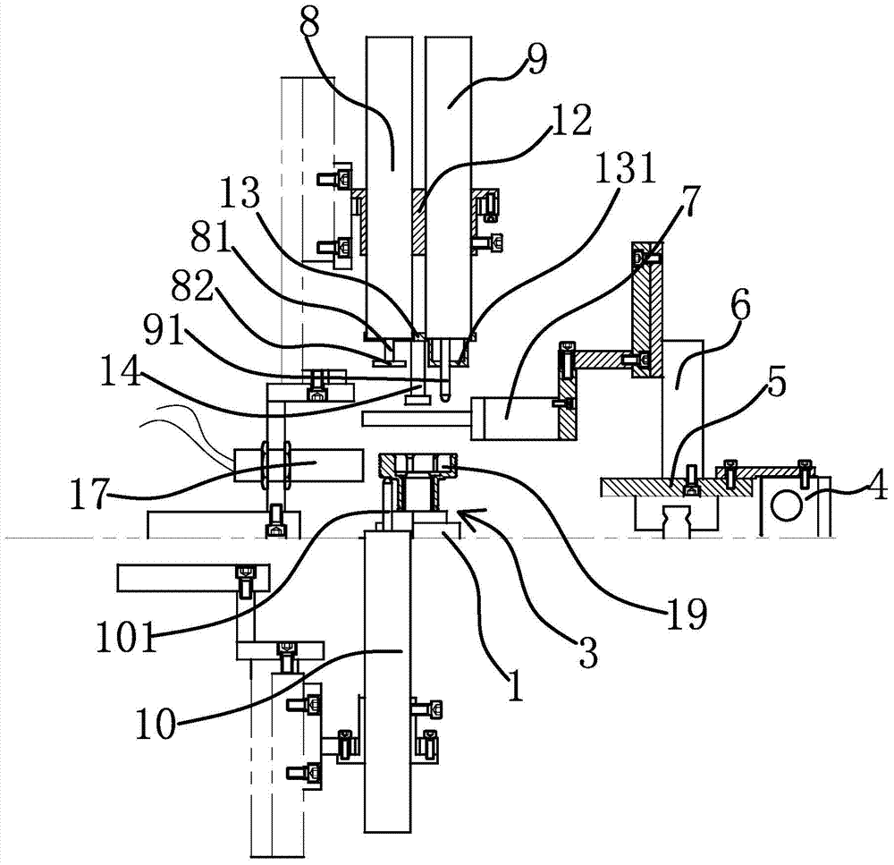
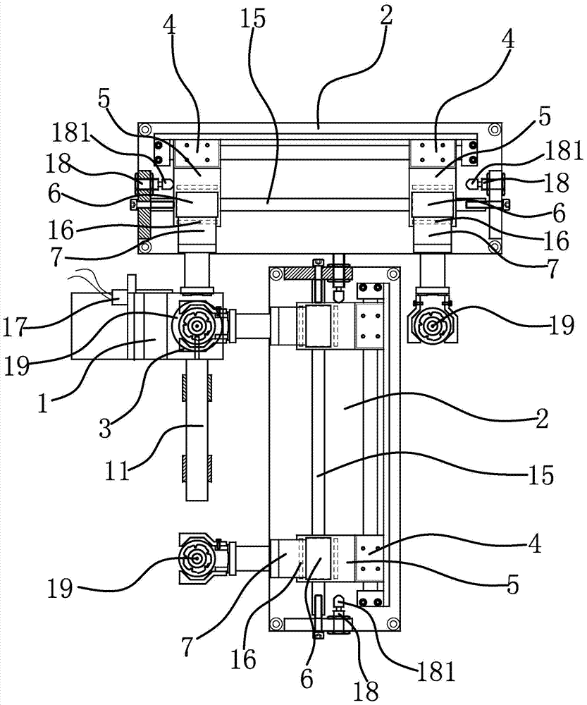
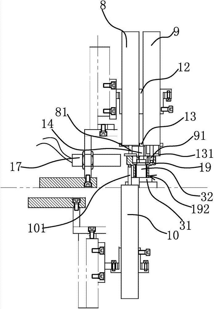
[0049] The on-line detection device for mechanical processing of the directional sleeve of the overrunning clutch is arranged on the production line of the directional sleeve 19, and is used for measuring the dimensional parameters such as the length, depth and groove diameter of the directional sleeve 19 processed by the CNC processing equipment. The on-line detection device for mechanical processing of the directional sleeve of the overrunning clutch includes a detection platform 1, a conveying platform 2, a workpiece positioning seat 3, a rodless cylinder 4, a bottom plate 5, a lifting cylinder 6, a finger cylinder 7, a total length detection sensor 8, and a depth detection sensor 9. Length detection sensor 10 and groove diameter detection sensor 11 .
[0050] Specifically, as figure 1 and Figure 5 As shown, the workpiece positioning seat 3 is arranged on the detection platform 1. The workpiece positioning seat 3 includes a seat body 31 fixed on the detection platform 1. ...
Embodiment 2
[0060] The on-line detection method for the machining of the directional sleeve of the overrunning clutch utilizes the online detection device for the machining of the directional sleeve of the overrunning clutch described in Embodiment 1 to detect the size of the directional sleeve 19 during the machining process. Specifically, as Image 6 shown, including the following steps:
[0061] A. Retrieving of the directional sleeve: the finger cylinder 7 clamps the directional sleeve 19 after the CNC processing equipment has been processed, and the rodless cylinder 4 drives the finger cylinder 7 to transport the directional sleeve 19 along the conveying platform 2 to the detection platform 1. The cylinder 7 places the workpiece on the workpiece positioning seat 3 .
[0062] As a preferred solution, in step A, when the photoelectric detection of the directional sleeve 19 is delayed, a signal is sent to the rodless cylinder 4 to stop the movement of the rodless cylinder 4, and the da...
Embodiment 3
[0074] The technical solution in this embodiment is basically the same as the solution in Embodiment 2, the difference is that in this embodiment, such as Figure 7 As shown, step D is carried out between step A and step B.
PUM
 Abstract
Description
Claims
Application Information
 - R&D
- Intellectual Property
- Life Sciences
- Materials
- Tech Scout
- Unparalleled Data Quality
- Higher Quality Content
- 60% Fewer Hallucinations
Browse by: Latest US Patents, China's latest patents, Technical Efficacy Thesaurus, Application Domain, Technology Topic, Popular Technical Reports.
© 2025 PatSnap. All rights reserved.Legal|Privacy policy|Modern Slavery Act Transparency Statement|Sitemap|About US| Contact US: help@patsnap.com


