Plate-type denitration catalyst
A denitration catalyst and a flat-plate technology, applied in the field of denitration technology, can solve the problems of easy wear, high manufacturing cost, low utilization efficiency, etc., and achieve the effects of high wear resistance, improved activity and service life, and simple recycling.
- Summary
- Abstract
- Description
- Claims
- Application Information
AI Technical Summary
Problems solved by technology
Method used
Image
Examples
Embodiment 1
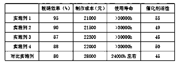
[0030] The flat plate denitration catalyst of the present invention is composed of a base material and a catalyst material arranged on the base material. The catalyst material includes titanium dioxide, vanadium pentoxide, ammonium heptamolybdate, lactic acid, glass fiber and silicon dioxide, wherein the base material is Stainless steel wire mesh with a mesh density of 90% and a mesh diameter of 1.0mm. Among them, the mass content of each component of the catalyst material is 75% titanium dioxide, the particle size is 10-15nm, 3% vanadium pentoxide, heptamolybdic acid Ammonia 11%, Lactic Acid 5%, Glass Fiber 5%, Silica 4%. Mix titanium dioxide, vanadium pentoxide, ammonium heptamolybdate, lactic acid, glass fiber and silicon dioxide evenly, and coat it on the base material stainless steel wire mesh. The thickness of the formed coating layer is 0.9mm, according to the set size After cutting and assembling, put it into an electric kiln for high-temperature sintering at a sinteri...
Embodiment 2
[0033] In this embodiment, the base material is stainless steel wire mesh, the mesh density is 90%, and the mesh diameter is 1.0mm, wherein, the mass content of each component is titanium dioxide 80%, particle size is 15-20nm, vanadium pentoxide 1%, ammonium heptamolybdate 7%, lactic acid 2%, glass fiber 5%, silicon dioxide 5%. Mix titanium dioxide, vanadium pentoxide, ammonium heptamolybdate, lactic acid, glass fiber and silicon dioxide evenly, and coat it on the base material stainless steel wire mesh. The thickness of the formed coating layer is 0.9mm, according to the set size After cutting and assembling, put it into an electric kiln for high-temperature sintering at a sintering temperature of 80-120°C for 8 hours, take it out, and cool it down to obtain the flat-plate denitration catalyst of this embodiment.
Embodiment 3
[0035] The base material is stainless steel wire mesh with a mesh density of 90% and a mesh diameter of 1.0mm. Among them, the mass content of each component is 85% titanium dioxide, the particle size is 20-25nm, 1.5% vanadium pentoxide, heptamolybdenum Ammonium acid 7%, lactic acid 1.5%, glass fiber 3.5%, silicon dioxide 1.5%. Mix titanium dioxide, vanadium pentoxide, ammonium heptamolybdate, lactic acid, glass fiber and silicon dioxide evenly, and coat it on the base stainless steel wire mesh. The thickness of the formed coating layer is 0.8mm, according to the set size After cutting and assembling, put it into an electric kiln for high-temperature sintering at 200-280° C. for 7 hours, take it out, and cool it down to obtain the flat-plate denitration catalyst of this embodiment.
PUM
| Property | Measurement | Unit |
|---|---|---|
| particle diameter | aaaaa | aaaaa |
| thickness | aaaaa | aaaaa |
| length | aaaaa | aaaaa |
Abstract
Description
Claims
Application Information
 - R&D
- Intellectual Property
- Life Sciences
- Materials
- Tech Scout
- Unparalleled Data Quality
- Higher Quality Content
- 60% Fewer Hallucinations
Browse by: Latest US Patents, China's latest patents, Technical Efficacy Thesaurus, Application Domain, Technology Topic, Popular Technical Reports.
© 2025 PatSnap. All rights reserved.Legal|Privacy policy|Modern Slavery Act Transparency Statement|Sitemap|About US| Contact US: help@patsnap.com

