Eureka AIR delivers breakthrough ideas for toughest innovation challenges, trusted by R&D personnel around the world.

Storage-tank cylindrical-section integral wallboard creep aging forming method

A technology of creep aging forming and cylindrical section, applied in forming tools, metal processing equipment, manufacturing tools, etc. To avoid problems such as degree deviation, achieve high dimensional accuracy, good formability, and small size deviation

Active Publication Date: 2015-04-08
CAPITAL AEROSPACE MACHINERY +1
View PDF6 Cites 9 Cited by
  • Summary
  • Abstract
  • Description
  • Claims
  • Application Information

AI Technical Summary

Problems solved by technology

[0003] In launch vehicles, tanks are generally hollow and thin-walled cylindrical structures. Each tank is welded by two ellipsoidal bottoms, short shells and several cylindrical sections. The traditional method of processing cylindrical sections is to The cylinder section is divided into several wall panels, which are formed separately, and then the multiple formed wall panel parts are welded into a cylinder section. The wall panels produced by the traditional method have two major disadvantages in the assembly of the storage tank. One is There are many welds in the cylinder section welded by multiple wall panels; second, in the subsequent assembly process, more welds accumulate, resulting in certain deviations in the straightness and roundness of the busbars of different cylinder sections
These have a certain impact on the high reliability of the rocket
At present, there are no relevant reports at home and abroad on the application of creep aging forming technology to the integral wall plate forming of launch vehicle tanks

Method used


Image

  • Storage-tank cylindrical-section integral wallboard creep aging forming method
  • Storage-tank cylindrical-section integral wallboard creep aging forming method
  • Storage-tank cylindrical-section integral wallboard creep aging forming method

Examples


Embodiment Construction

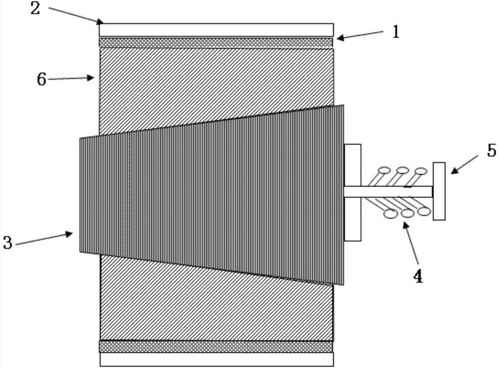
[0023] The method for integral creep aging forming of the wall plate of the tank cylinder section according to the present invention will be further described below in conjunction with the accompanying drawings and specific embodiments.

[0024] A method for integral creep aging forming of a tank cylinder section wall plate according to the present invention comprises the following steps:

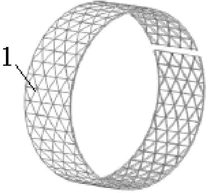
[0025] (a) if figure 1 As shown, the wall plate of the cylindrical section of the storage tank is processed according to the drawing size, and the inner grid or outer grid of the wall plate is milled to meet the size requirements; then the wall plate 1 is pre-rolled on the rolling bending equipment;

[0026] (b) welding the wall plate 1 obtained in step (a) along the longitudinal seam into an integral cylindrical wall plate; the cylindrical wall plate has only one welding seam;

[0027] (c) Carry out finite element simulation of creep aging forming (using existing technology, such as: ABAQ...


PUM


Abstract

The invention provides a storage-tank cylindrical-section integral wallboard creep aging forming method. The method includes the steps of a), subjecting a storage-tank cylindrical-section wallboard to machining according to drawing dimension, milling an interior grid or an exterior grid of the wallboard to dimensional requirements and then subjecting the wallboard to pre-roll bending on roll bending equipment; b), welding the wallboard to an integral cylindrical wallboard along a longitudinal joint; c), performing finite element modeling subjected to creep aging forming, calculating stress to be borne by a sticking mold of the cylindrical-section wallboard after welding, meanwhile, calculating rebound quantity and manufacturing a forming mold according to the stress and the rebound quantity; d), placing the wallboard into the mold and applying forming pressure by the mechanical mode; e), placing the assembled mold into an aging furnace for heat preservation at the temperature ranging from 150 to 200 DEG C for 10-30 hours, and then taking out the mold from the aging furnace to obtain a cylindrical-section wallboard product. With the method, the storage-tank cylindrical-section integral wallboard is formed and welded at one step, the number of welding joints is reduced, and reliability in tank storage is improved.

Description

technical field [0001] The invention relates to the field of metal plastic forming, in particular to the integral forming of the wall plate of the carrier rocket storage tank, and in particular to an integral creep aging forming method for the wall plate of the cylindrical section of the storage tank. Background technique [0002] Creep aging forming is a green and environmentally friendly advanced manufacturing technology developed in recent years, that is, a forming method that uses the creep characteristics of metals to synchronize forming and aging. Creep forming, the artificial aging strengthening of the material is completed at the same time as forming, the microstructure of the material is improved, and the strength performance of the material is improved; the forming stress is generally lower than the yield strength of the material, which avoids the material from entering the yield state The phenomenon of possible instability or even cracking greatly reduces the prob...

Claims


Application Information

Patent Timeline
Patent Type & Authority Applications(China)
IPC IPC(8): B23P15/00B21D37/10
CPCB23P15/00
Inventor 万李丁鹏飞周世杰祝世强李杰林建国
Owner CAPITAL AEROSPACE MACHINERY
Why Eureka
Eureka Blog
Learn More