A fast saturable reactor
A reactor and fast technology, applied in the direction of inductors, variable inductors, circuits, etc., can solve the problems of complex process requirements and high symmetry requirements of the iron core of magnetically controlled saturated reactors, and achieve simple methods and processes, The effect of reducing the requirement of symmetry and speeding up the adjustment response speed
- Summary
- Abstract
- Description
- Claims
- Application Information
AI Technical Summary
Problems solved by technology
Method used
Image
Examples
Embodiment 1
[0040] The present invention will be further described below in conjunction with the accompanying drawings and embodiments.
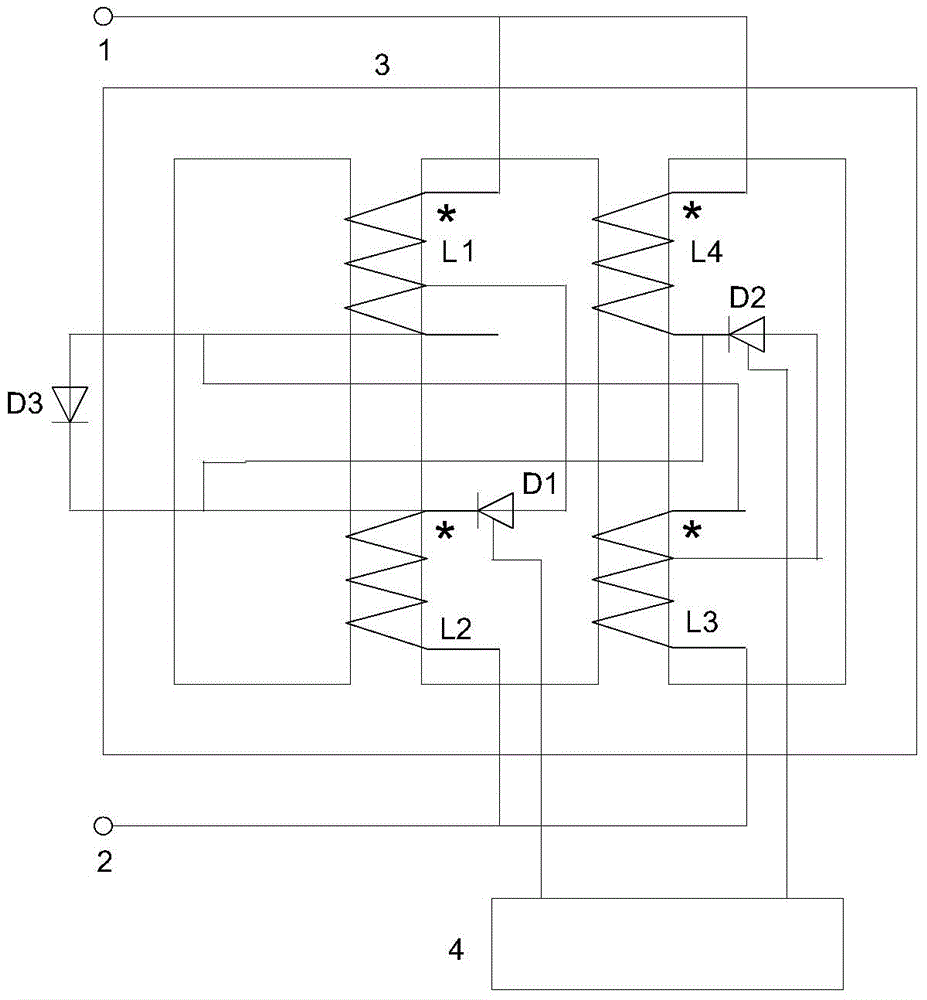
[0041] The structure and connection method of traditional saturable reactor are as follows: figure 1 shown. Traditional saturable reactors generally have the problem of slow response, and saturable reactors need taps, and the manufacturing process is complicated.
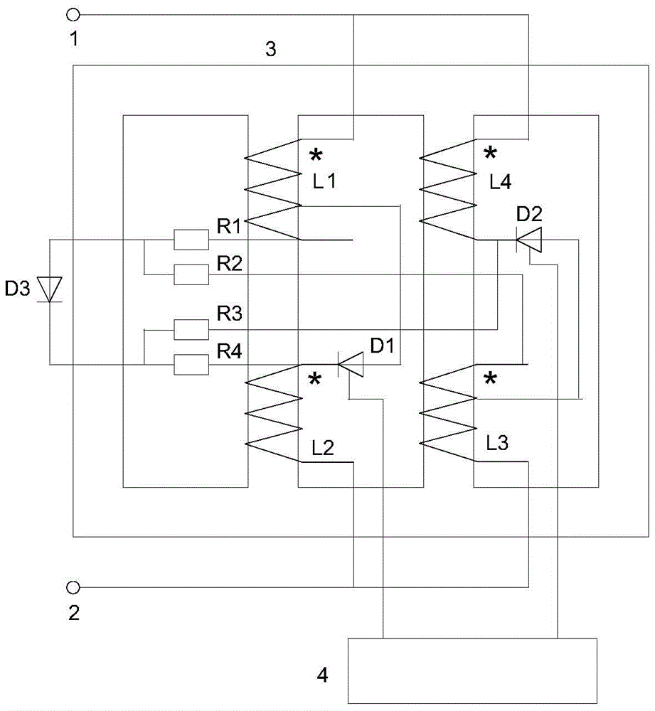
[0042] The structure and connection method of the first fast saturable reactor are as follows: figure 2 shown. Including fast saturable reactor terminal I1, fast saturable reactor terminal II2, fast saturable reactor closed-loop iron core 3, control circuit 4. The closed-loop iron core 3 of the fast saturable reactor has at least two iron core columns; there are two iron core columns with the same cross-sectional area, both of which have DC coils and AC coils; each of these two iron core columns can at least form a Closed loop of magnetic flux in the core leg. There is a DC coil L1 and ...
Embodiment 2
[0056] The present invention will be further described below in conjunction with the accompanying drawings and embodiments.
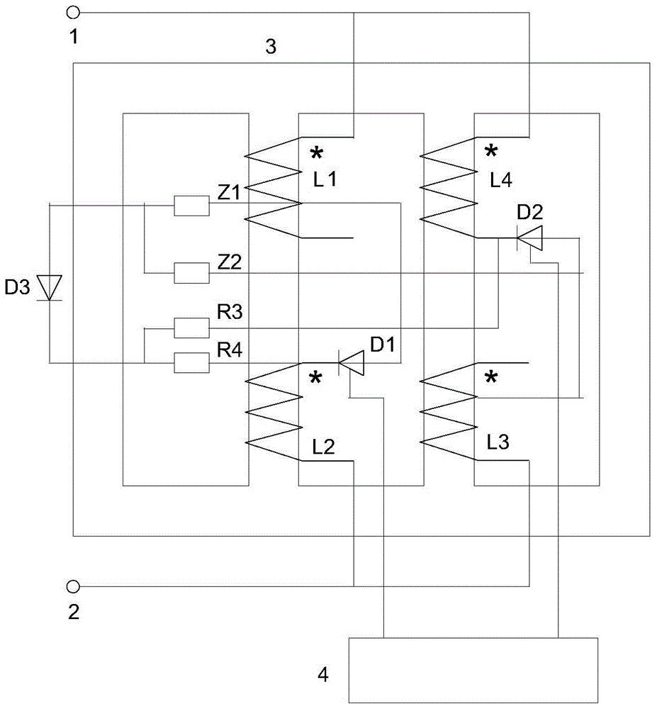
[0057] The structure and connection method of the second fast saturable reactor are as follows: image 3 shown. The same parts as in Embodiment 1 are no longer redundant. The different parts are described as follows.
[0058] Compared figure 2 and image 3 It can be seen that putting figure 2 This part of the coil from the DC coil L1 tap to the opposite end is removed, figure 2 The tap of the DC coil L1 becomes image 3 The opposite end of the DC coil L1; figure 2 The part of the DC coil L3 tapped to the end of the same name is removed, figure 2 The tap of the DC coil L3 becomes image 3 The terminal of the same name of the DC coil L3. figure 2 The DC coil L1 and the DC coil L3 respectively have three lead-out terminals, image 3 The DC coil L1 and the DC coil L3 respectively have only two lead-out terminals. The original tap becomes t...
PUM
 Abstract
Description
Claims
Application Information
 - R&D
- Intellectual Property
- Life Sciences
- Materials
- Tech Scout
- Unparalleled Data Quality
- Higher Quality Content
- 60% Fewer Hallucinations
Browse by: Latest US Patents, China's latest patents, Technical Efficacy Thesaurus, Application Domain, Technology Topic, Popular Technical Reports.
© 2025 PatSnap. All rights reserved.Legal|Privacy policy|Modern Slavery Act Transparency Statement|Sitemap|About US| Contact US: help@patsnap.com


