
Real-time Monitoring System of Concrete Abrasion and Cavitation Depth Based on Chirped Fiber Bragg Grating

A chirped fiber grating and concrete technology, applied in measurement devices, optical devices, instruments, etc., can solve the problems of no continuous monitoring, complex data analysis process, low precision, etc., to achieve quasi-distributed measurement, easy to form Sensor network, the effect of stable work

Active Publication Date: 2017-09-05
THE FRONTIER TECH RES INST OF TIANJIN UNIV
View PDF7 Cites 1 Cited by
  • Summary
  • Abstract
  • Description
  • Claims
  • Application Information

AI Technical Summary

Problems solved by technology

However, it is easy to induce serious water erosion problems in water conservancy and hydropower projects.
Tianjin University has developed a cavitation monitoring system for regionally distributed drainage structures. This invention meets the needs of quasi-distributed monitoring, but its data analysis process is very complicated, and it does not realize continuous monitoring.
In general, the few sensor monitoring systems in China currently have defects such as small monitoring range, incapable of long-term real-time monitoring, low precision, and cumbersome data processing. It is convenient for large-scale batch processing of monitoring data and easy to operate. Therefore, a new real-time monitoring system for concrete abrasion or cavitation depth is developed based on fiber grating sensors to achieve real-time measurement of the degree of abrasion (or cavitation) damage on the concrete surface. Especially in the concrete parts that are not easy to be directly observed, such as cave drainage structures and stilling basins, it is imperative

Method used


Image

  • Real-time Monitoring System of Concrete Abrasion and Cavitation Depth Based on Chirped Fiber Bragg Grating
  • Real-time Monitoring System of Concrete Abrasion and Cavitation Depth Based on Chirped Fiber Bragg Grating
  • Real-time Monitoring System of Concrete Abrasion and Cavitation Depth Based on Chirped Fiber Bragg Grating

Examples


Embodiment 1

[0028] The specific embodiments of the present invention will be described in detail below in conjunction with the technical solutions of the present invention and the accompanying drawings. Obviously, the described embodiment is only one embodiment of the present invention, not all embodiments. Based on the embodiments of the present invention, all other embodiments obtained by persons of ordinary skill in the art without making creative efforts belong to the protection scope of the present invention.

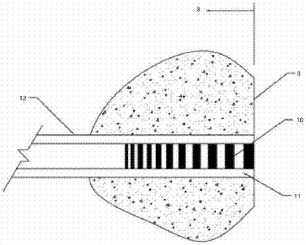
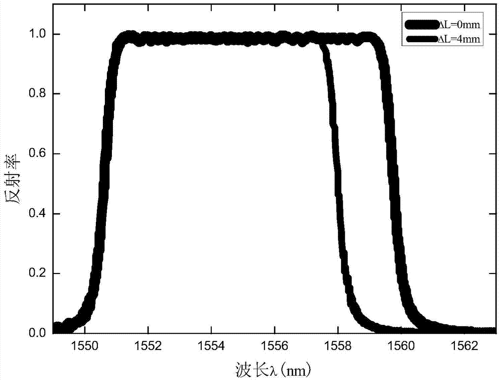
[0029] The structure of the real-time monitoring system for concrete abrasion and cavitation depth based on chirped fiber gratings of the present invention is as follows:figure 1 shown. The real-time monitoring system includes: a concrete structure surface 1 , a fiber grating sensor unit 2 , a data communication module 3 , and a computer monitoring unit 4 . The sensor unit is connected with the computer monitoring unit through the data communication module, and the data commun...


PUM


Abstract

The invention discloses a real-time monitoring system for concrete abrasion and cavitation depth based on a chirped optical fiber grating. The system includes a concrete structure surface, a chirped optical fiber grating sensor unit, a data communication module, and a computer monitoring unit; the chirped optical fiber The sensor group in the grating sensor unit is pre-embedded in the concrete perpendicular to the concrete surface during the construction of water conservancy and hydropower projects, and the top of the sensor group is flush with the concrete surface. Concrete erosion caused by water flow cavitation and other reasons; the end of the sensor group is connected to the computer monitoring unit through the data communication module, and the data communication module and the computer monitoring unit are connected by serial port. The invention has high testing precision, and its single-point depth measurement can reach sub-mm precision. The invention has the advantages of stable work, accurate information, intuitive display, and expandable use.

Description

technical field [0001] The invention belongs to the field of safe operation monitoring of water conservancy and hydropower projects, and in particular relates to a real-time monitoring system for concrete abrasion and cavitation depth based on chirped fiber gratings. The concrete surface erosion is monitored, and the monitoring data is analyzed and processed in real time to obtain the measurement system and method of the concrete erosion and cavitation depth and its position information. Background technique [0002] Water conservancy and hydropower projects, as one of the country's important infrastructures, are often subject to erosion and cavitation damage on the concrete surfaces of water-guiding and drainage structures due to the erosion of long-term water flow, especially sand-laden water flow. The further expansion of the depth of abrasion (cavitation erosion) will easily lead to the failure of structural joints, the exposure of steel bars, etc., and even endanger the...

Claims


Application Information

Patent Timeline
Patent Type & Authority Patents(China)
IPC IPC(8): G01B11/22
Inventor 夏开文潘永庆孙立强徐颖练继建
Owner THE FRONTIER TECH RES INST OF TIANJIN UNIV
Learn More