
Extruding device of 5083 aluminum alloy I beam

An extrusion device and I-beam technology, applied in the direction of metal extrusion dies, etc., can solve problems such as easy to generate waves, narrow space, and poor forming quality of I-beams, so as to reduce metal flow, improve forming quality, and increase The effect of metal supply

Inactive Publication Date: 2015-04-01
SOUTHWEST ALUMINUM GRP
View PDF11 Cites 0 Cited by
  • Summary
  • Abstract
  • Description
  • Claims
  • Application Information

AI Technical Summary

Problems solved by technology

[0004] However, during the forming process of the I-beam, because the I-beam cladding plate is thin and the space is narrow, the metal flow velocity at the cladding plate forming position is relatively fast, and the metal is prone to waves when flowing at the cladding plate forming position, so that after the cladding plate is formed The surface is a corrugated surface, resulting in poor forming quality of the I-beam

Method used


Image

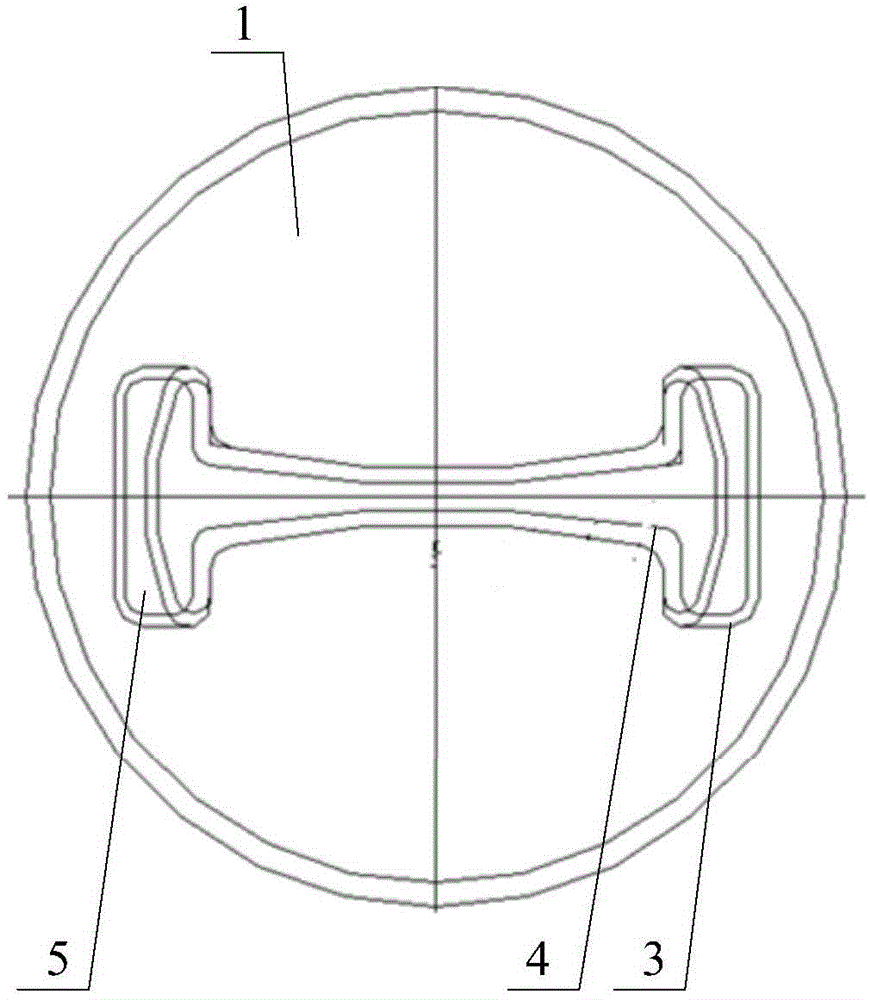
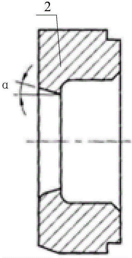
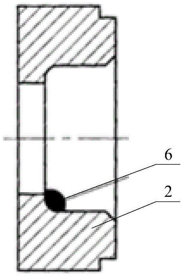
  • Extruding device of 5083 aluminum alloy I beam
  • Extruding device of 5083 aluminum alloy I beam
  • Extruding device of 5083 aluminum alloy I beam

Examples


Embodiment Construction

[0019] The core of the present invention is to provide a 5083 aluminum alloy I-beam extrusion device, which can improve the forming quality of the 5083 aluminum alloy I-beam.

[0020] In order to enable those skilled in the art to better understand the technical solutions of the present invention, the present invention will be further described in detail below with reference to the accompanying drawings and embodiments.

[0021] Please refer to Figure 1 to Figure 3 In a specific embodiment, the 5083 aluminum alloy I-beam extrusion device provided by the present invention includes a die body 1, a guide die 3 arranged on the die body 1, and a main flow cavity is provided on the guide die 3 And the auxiliary diversion cavity 5 arranged at both ends of the main flow cavity and communicated with the main flow cavity. The size of the auxiliary diversion cavity 5 is determined according to actual conditions. The mold body 1 is provided with a mold hole 4, and both the main flow cavity a...


PUM


Abstract

The invention discloses an extruding device of a 5083 aluminum alloy I beam. The extruding device comprises a mold body and a guide mold which is arranged on the mold body, wherein the guide mold is provided with a main guide cavity and auxiliary guide cavities which are arranged on two ends of the main guide cavity and communicated with the main guide cavity. A mold hole is formed in the mold body, and both the main guide cavity and auxiliary guide cavity are respectively communicated with the mold hole. In the extruding device of the 5083 aluminum alloy I beam, the flow area of the guide cavity on the guide mold is increased by arranging the auxiliary guide cavities, the auxiliary guide cavities are arranged on two ends of the main guide cavity, and inlets, in which a wing plate is formed, are formed in two ends of the main guide cavity, so that the metal supply amount of the position on which the wing plate is formed can be increased, the flow rate of metal of the position on which a shroud plate is arranged can be reduced, and the corrugation situation formed by the flow of the metal liquid on the position of the shroud plate can be reduced; therefore, the forming quality of the 5083 aluminum alloy I beam can be improved by the extruding device.

Description

Technical field [0001] The present invention relates to the technical field of I-beam processing, in particular to a 5083 aluminum alloy I-beam extrusion device. Background technique [0002] 5XXX series aluminum alloys are aluminum alloys with magnesium as the main alloy element. Among non-heat-treatable alloys, they have good strength, good corrosion resistance and machinability, and are widely used in technical fields such as ship, automobile and aircraft welding parts. Among them, the 5083 aluminum alloy I-beam is formed by extrusion, stretching and roll correction, and the 5083 aluminum alloy I-beam (hereinafter referred to as the I-beam) is formed by an extrusion device. [0003] The traditional extrusion device is provided with die holes, and the metal solution enters and exits the die through the die holes. When the I-beam is formed, the liquid metal enters the mold through the die hole inlet, and finally is discharged through the die hole outlet. [0004] However, during t...

Claims


Application Information

Patent Timeline
Patent Type & Authority Applications(China)
IPC IPC(8): B21C25/02
CPCB21C25/02
Inventor 裘桢
Owner SOUTHWEST ALUMINUM GRP
Learn More