
A ceramic wire/cable core manufacturing system

A technology for manufacturing systems and cable cores, applied in cable/conductor manufacturing, circuits, electrical components, etc., can solve problems such as difficult to achieve high-speed production of ceramic wires and cables, and achieve market competitiveness, continuous production, and simple process equipment Effect

Active Publication Date: 2017-04-19
SHENZHEN WOER HEAT SHRINKABLE MATERIAL +1
View PDF8 Cites 0 Cited by
  • Summary
  • Abstract
  • Description
  • Claims
  • Application Information

AI Technical Summary

Problems solved by technology

[0007] The purpose of the present invention is to provide a ceramic wire / cable core manufacturing system to solve the problem that the existing production equipment is difficult to realize the high-speed production of ceramic wire and cable. The technical scheme of the present invention is as follows:

Method used


Image

  • A ceramic wire/cable core manufacturing system
  • A ceramic wire/cable core manufacturing system

Examples


Embodiment 1

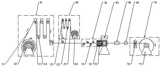
[0041] see figure 1, which discloses the longitudinal wrapping mechanism (embodiment 1) of the ceramic wire / cable core manufacturing system of the present invention, including a series-connected storage and release unit 10, a longitudinal wrapping unit 30, and a set of sheath layer extruding unit 40 , cooling and heating unit 50, high-voltage spark machine 60, system equipment of take-up unit 70 and parallel storage and feeding belt unit 20.

[0042] The wire storage and release unit 10 includes an active wire release mechanism 12, a wire / cable core 11, a pair of movable rollers B 14 and three fixed rollers A 13. The arrangement enables the movable roller B 14 to move freely up and down.

[0043] The longitudinal swivel unit 30 includes four fixed roller sets E 31 , the horn bundle mold 32 and the wire / cable core 11, in order of the direction of travel of the wire / cable core 11, the fixed roller set E 31 is connected in series to the horn The upstream of the bundle mold 32 a...

Embodiment 2

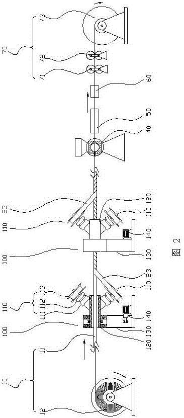
[0049] see figure 2 , which discloses the winding and covering mechanism (embodiment 2) of the ceramic wire / cable core manufacturing system of the present invention, including the storage and release line unit 10 in series, two winding units 100 clockwise and counterclockwise, a set of protective Jacket extruding unit 40, cooling and heating unit 50, high-voltage spark machine 60, take-up unit 70" system equipment.

[0050] The pay-off unit 10 includes an active pay-off machine 12, a wire / cable core 11 and a tension control system 71. The tension control system 71 is arranged at the take-up end. The pay-off mechanism 12 and the tension control system 71 use PLC to control the line speed and tension.

[0051] The winding unit 100 includes a belt feeding mechanism 110, a revolving hollow shaft 120, a bracket 130 and a revolving motor 140; in order of the direction of travel of the wire / cable core 11, two sets of winding units 100 are immediately adjacent to and connected in ser...


PUM


Abstract

The invention discloses a ceramic electric wire / cable core manufacturing system. The ceramic electric wire / cable core manufacturing system comprises a longitudinal rotary wrapping mechanism and a twisting coating mechanism. The longitudinal rotary wrapping mechanism is formed by connecting equipment and at least one band storing and feeding unit (20) in series, wherein the equipment comprises a wire storage and pay-off unit (10), at least one longitudinal rotary wrapping unit (30), at least one sheath layer extrusion unit (40), a cold and hot unit (50), a high-voltage spark machine (60) and a take-up unit (70), and the wire storage and pay-off unit (10), the longitudinal rotary wrapping unit (30), the sheath layer extrusion unit (40), the cold and hot unit (50), the high-voltage spark machine (60) and the take-up unit (70) are connected in series. The twisting coating mechanism is composed of equipment comprising a wire storage and pay-off unit (10), at least one twisting unit (100), at least one sheath layer extrusion unit (40), a cold and hot unit (50), a high-voltage spark machine (60) and a take-up unit (70), wherein the wire storage and pay-off unit (10), the twisting unit (100), the sheath layer extrusion unit (40), the cold and hot unit (50), the high-voltage spark machine (60) and the take-up unit (70) are connected in series.

Description

technical field [0001] The invention belongs to the technical field of electric wire and cable manufacturing, and relates to a manufacturing system suitable for manufacturing electric wire / cable cores with ceramic silicon rubber compound tapes. Background technique [0002] In recent years, with the invention of ceramic silicone rubber, it is suitable for the manufacture of wires and cables used in the periphery of aero-engines, launch and recovery of spacecraft, and power supply systems in various fields of industrial and civil buildings. In extreme environments, the fire resistance rating and normal power supply reliability of wires and cables are raised to unprecedented liquid levels. [0003] However, if ceramic silicone rubber is used to directly extrude wires and cables, in order to avoid cracks on the surface of the extruded layer of ceramic silicone rubber, it can only be produced at a lower extrusion speed, which reduces the work efficiency of the original wire and ...

Claims


Application Information

Patent Timeline
Patent Type & Authority Patents(China)
IPC IPC(8): H01B13/26
Inventor 王志勇肖扬华
Owner SHENZHEN WOER HEAT SHRINKABLE MATERIAL
Learn More