


Quick Research
Generate reliable direction feasibility study reports for your R&D in just a few steps.

Technical Q&A
Discover and master advanced knowledge NOW. Basics, ideas, possibilities, all at once.

Find Solutions
As an expert in R&D theories, this can generate solutions to your technical problems instantly.

Evaluate Feasibility
Analyze your overall solution with one click, know your potential R&D risks in advance.

Monitor Landscape
Get weekly tech updates, stay abreast of the latest tech innovations and key insights.
Frame complex work condition multi-axial fatigue calculation method including welding simulation
A technology for welding simulation and complex working conditions, applied in the field of fatigue calculation, can solve the problems of saving resources, social progress, repeated research and development, disadvantages, etc., to avoid repeated research and development, improve accuracy, and save resources.
- Summary
- Abstract
- Description
- Claims
- Application Information
AI Technical Summary
Problems solved by technology
Method used
Image

Examples
Embodiment 1
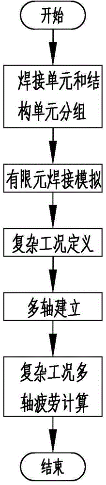
[0036] Embodiment 1, a method for calculating multi-axis fatigue under complex working conditions of frame overturning moment fatigue including welding simulation, comprising the following steps:
[0037] S1, grouping of welding units and structural units: set the spatial coordinate system of X, Y, Z and coordinate origin, and group welding units and structural units;
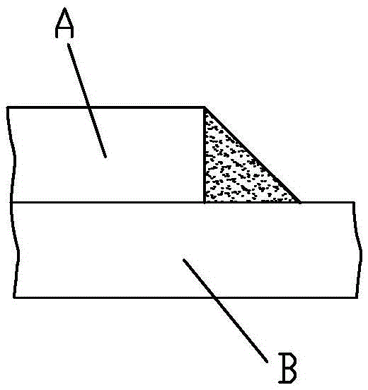
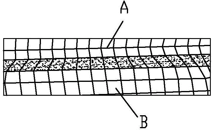
[0038] S2, finite element welding simulation: perform finite element welding simulation on sheet metal welding and surface welding in the form of fillet welds; among them, the welding unit adopts a quadrilateral grid with a side length of 3 to 5mm; the warpage of the grid is less than 5%; there is no triangular mesh in the weld layer, and the proportion of triangular mesh in the grid units of the welding connection layer adjacent to the weld layer is less than 5%; it is best that there is no mesh warping at the start and end of the fillet weld Curved elements and triangular mesh elements, the edges of the weld ...
Embodiment 2
[0045]Embodiment 2, a multi-axial fatigue calculation method for S-shaped steering tilting fatigue complex working conditions including welding simulation, including S1 welding unit and structural unit grouping; S2 finite element welding simulation; S3 complex working condition definition; S4 multi-axis establishment and S5 multiaxial fatigue calculation steps;
[0046] Among them, the definition of complex working conditions includes defining S-shaped steering overturning fatigue loads and fatigue cycle conditions; the fatigue loads include the size, direction and loading position of the load; the fatigue load size of the S-shaped steering overturning fatigue conditions , direction, loading position and other load parameters can be obtained through the snake test to obtain the attitude parameters of the vehicle, that is, the pitch, lateral bending angle, tipping moment and acceleration parameters; the simulation parameters can also be obtained by multi-body dynamics software; ...
Embodiment 3
[0049] Embodiment 3, a multi-axis fatigue calculation method for continuous brake tilting fatigue complex working conditions including welding simulation, including S1 welding unit and structural unit grouping; S2 finite element welding simulation; S3 complex working condition definition; S4 multi-axis establishment and S5 multiaxial fatigue calculation steps;
[0050] Among them, the definition of complex working conditions includes the definition of S-shaped steering overturning fatigue loads and fatigue cycle conditions; the fatigue load includes the magnitude, direction and loading position of the load; wherein, the fatigue load size of the continuous brake overturning fatigue condition , direction, and loading position are, in order to load the mechanical parameters of eight loads including the braking force and torque of the front left, front right, rear right, and rear left wheels on the connection position between the frame and the suspension, and ensure that the force ...
PUM
 Abstract
Description
Claims
Application Information
 - R&D Engineer
- R&D Manager
- IP Professional
- Industry Leading Data Capabilities
- Powerful AI technology
- Patent DNA Extraction
Browse by: Latest US Patents, China's latest patents, Technical Efficacy Thesaurus, Application Domain, Technology Topic, Popular Technical Reports.
© 2024 PatSnap. All rights reserved.Legal|Privacy policy|Modern Slavery Act Transparency Statement|Sitemap|About US| Contact US: help@patsnap.com