A split tunnel kiln

A tunnel kiln and split-type technology, applied in the field of tunnel kiln, can solve the problems of inability to realize continuous mass production, excessive one-time investment, cold or hot frying of products, etc. The effect of improving the utilization of the site and improving the production efficiency

Active Publication Date: 2016-07-27
彭州市半陶陶瓷有限责任公司
View PDF8 Cites 1 Cited by
  • Summary
  • Abstract
  • Description
  • Claims
  • Application Information

AI Technical Summary

Problems solved by technology

[0004] It can be seen that the existing tunnel kiln is a fully ventilated linear structure. Because it is a fully ventilated structure, the cooling zone is greatly affected by the surrounding environment. If the temperature of the cooling zone is not properly controlled, it will be too fast or too Slowing down can easily lead to cold or hot frying of products, and the damage rate is very high; in addition, the length of the tunnel kiln is usually 80 meters to 100 meters, and some tunnel kilns are 100 meters to 200 meters long, so the requirements for the site are very high. Among them, the length of the cooling zone accounts for about half of the total length of the tunnel kiln, and the finished products are produced at one time through the tunnel kiln. Only after the products in the cooling zone leave the kiln, can the products in the firing zone enter the cooling zone for cooling, which cannot be achieved. Continuous mass production in the true sense; moreover, for different products, the roasting process must be completely changed, the one-time investment is too large, and the technical requirements for production are very strict. Since it is a continuous firing kiln, the structure cannot be arbitrary Changes, which are only suitable for mass production and products that have basically the same requirements for the firing system, the scope of application is narrow, and the flexibility is poor

Method used


Image

  • A split tunnel kiln
  • A split tunnel kiln
  • A split tunnel kiln

Examples


Embodiment Construction

[0019] In order to understand the purpose, technical solutions and beneficial effects of the present invention more clearly, the present invention will be further described below in conjunction with the accompanying drawings, but the protection scope of the present invention is not limited to the following embodiments.

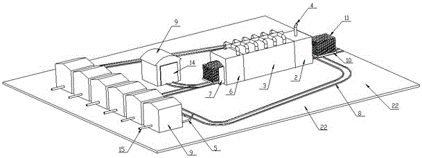
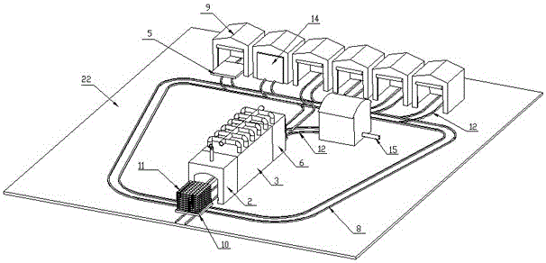
[0020] Such as Figure 1 to Figure 3 As shown, a split tunnel kiln includes: a kiln body 1 set on an earthwork foundation 22, the kiln body 1 is formed by connecting walls on both sides and an arch at the top, and the kiln body 1 is built on a platform The running direction of the car 10 is divided into a preheating chamber 2 and a firing chamber 3 in turn, wherein a flue 4 for releasing flue gas is arranged above the preheating chamber 2, and a heating device is arranged in the firing chamber 3 to burn The upper part of the chamber 3 is a high-temperature zone, and the lower part is a low-temperature zone. The kiln end of the kiln body 1 leaves a section as a tra...


PUM


Abstract

The invention discloses a split type tunnel kiln. A kiln body (1) is divided into a preheating chamber (2) and a sintering chamber (3) in the moving direction of a trolley (10). Cooling chambers (9) of the tunnel kiln are arranged around the kiln body (1) and separated from the sintering chamber (3). Sintered products (11) coming out of the sintering chamber (3) are conveyed to the cooling chambers (9) through a transfer trolley (5) which moves back and forth between a transfer chamber (6) and the cooling chambers (9). The split type tunnel kiln can improve production efficiency greatly, products of different technological requirements are sent to different cooling chambers for cooling, so that the situation that the baking process of the whole tunnel kiln is changed completely due to different technological requirements of different products is avoided, cold breakage or hot breakage caused by improper temperature control is avoided, the qualified rate of the products is improved, investment is saved, and the application range is wide.

Description

Technical field [0001] The invention relates to a tunnel kiln. Background technique [0002] Tunnel kiln is a modern continuous firing thermal equipment, which is widely used in the firing production of ceramic products and bricks, and is also used in metallurgical industries such as abrasives. [0003] The current tunnel kiln structure is usually a very long linear tunnel with fixed walls and vaults on both sides and the top, and the bottom is laid with a moving track for carrying the kiln car. The tunnel kiln is divided into the moving direction of the kiln car. There are three areas, namely the preheating zone, the firing zone and the cooling zone. The two sides of the tunnel kiln are equipped with combustion equipment to form a fixed high temperature zone, also called the firing zone. The high temperature flue gas generated by the combustion equipment is in the tunnel. Under the action of the chimney or induced draft fan at the front of the kiln, it flows along the direction o...

Claims


Application Information

Patent Timeline
Patent Type & Authority Patents(China)
IPC IPC(8): F27B9/02F27B9/12F27B9/14F27B9/30
Inventor 李世建吴志章
Owner 彭州市半陶陶瓷有限责任公司
Why Eureka
Try Eureka