
Heating and ventilation control valve with automatic monitoring function

An automatic monitoring and control valve technology, applied in the field of mechanical parts, can solve the problems of high manufacturing and use costs, complex automatic monitoring structure, and power consumption, etc., and achieve the effects of low cost, wide-scale promotion and use, and real-time monitoring

Inactive Publication Date: 2015-03-25
TIANJIN GINGFLYING TECH
View PDF2 Cites 0 Cited by
  • Summary
  • Abstract
  • Description
  • Claims
  • Application Information

AI Technical Summary

Problems solved by technology

The automatic monitoring structure of this structure is too complicated, the cost of manufacture and use is too high, and the use is also very cumbersome, which consumes power and wastes resources.

Method used


Image

  • Heating and ventilation control valve with automatic monitoring function

Examples


Embodiment Construction

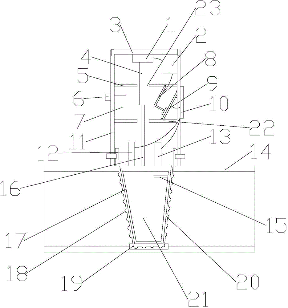
[0010] The following is attached figure 1 The present invention is further described:

[0011] In the figure: 1-cylinder, 2-motor, 3-cover, 4-piston, 5-first pallet, 6-timer, 7-flow monitor, 8-carbon brush, 9-control circuit board, 10 -display screen, 11-cover body, 12-temperature sensor, 13-humidity sensor, 14-valve body, 15-flow detector, 16-valve stem, 17-spool, 18-anti-skid protrusion, 19-valve seat , 20-rubber bushing, 21-inverted trapezoidal cavity, 22-second supporting plate, 23-through groove.

[0012] The present invention comprises a valve body 14, a valve seat 19 is arranged on the bottom of the valve body 14, a valve core 17 is arranged on the top of the valve seat 19, an inverted trapezoidal cavity 21 is arranged inside the valve core 17, and the outer surface of the valve core 17 is covered with rubber Bushing 20, the outer surface of the rubber bushing 20 is provided with anti-slip protrusions 18, the upper surface of the valve body 14 is provided with a cover...


PUM


Abstract

The invention belongs to the field of mechanical components and particularly relates to a heating and ventilation control valve with automatic monitoring function. An inverted trapezoidal cavity is formed in a valve element. The valve element is sleeved with a rubber bushing. Anti-skid protrusions are arranged on the outer surface of the rubber bushing. A cover body is arranged on the valve body. A cover cap is arranged at the top of the cover body. An air cylinder is arranged on the lower bottom face of the cover cap. A piston of the air cylinder is connected with a valve rod. The middle of a first layer board and the middle of a second layer board are each provided with a through groove. A motor is arranged on the side wall of the cover body. The air cylinder is connected with the motor. A control circuit board is arranged between the first layer boar and the second layer board. One end of the control circuit board is welded to the inner wall of the cover body, and the other end of the control circuit board is welded to the second layer board. A display screen is arranged on the outer surface of the cover cap. The control circuit board is connected with the motor and the display screen respectively. A carbon brush is hinged to the second layer board. The carbon brush is connected with the motor and opposite to the control circuit board.

Description

technical field [0001] The invention belongs to the field of mechanical components, and in particular relates to an automatic monitoring HVAC control valve. Background technique [0002] The HVAC control valve, also known as the lock valve and the special valve for civil heating, is mainly used to facilitate property management, and residents can independently adjust the temperature and time of heating. It is an environmentally friendly and automatic monitoring product. However, the currently used valves have poor sealing properties, complex structures, high manufacturing costs, and cumbersome use. [0003] For example, Chinese patent 03178535.2 discloses an automatic monitoring valve, which involves a valve device, which is composed of a valve body, a valve core, and a valve stem, and is characterized in that the periphery of the sealing sheet of the software is pressed on the step between the lower part of the spiral sleeve and the upper part of the valve body Between the...

Claims


Application Information

Patent Timeline
Patent Type & Authority Applications(China)
IPC IPC(8): F16K31/02F16K3/30F16K37/00
CPCF16K3/22F15B21/08F16K3/314F16K31/122F16K37/0075F16K37/0091
Inventor 蔡敏
Owner TIANJIN GINGFLYING TECH
Learn More