
Spacecraft damping vibration isolation micro-vibration test chamber

A micro-vibration, spacecraft technology, applied in vibration testing, machine/structural component testing, sound insulation, etc., can solve problems such as reducing equipment technical performance indicators, background noise that cannot meet test requirements, and inability to meet test accuracy requirements, etc. The effect of improving the existing level of micro-vibration testing

Inactive Publication Date: 2015-03-25
BEIJING INST OF SPACECRAFT ENVIRONMENT ENG
View PDF8 Cites 14 Cited by
  • Summary
  • Abstract
  • Description
  • Claims
  • Application Information

AI Technical Summary

Problems solved by technology

As there is currently no ultra-quiet site available, background noise isolation is usually achieved by turning off the air conditioner and reducing the impact of people walking, but the background noise still cannot meet the test requirements, and the technical indicators related to the equipment cannot be verified on site. The background noise is greater than 8mN, which cannot meet the requirements. 0.1mN test accuracy requirement
[0007] Based on the above analysis, it can be known that background noise directly affects the accuracy of micro-vibration testing. Due to the very high requirements for the accuracy of micro-vibration testing of interference sources, the current laboratory environment has greatly reduced the technical performance indicators of related equipment. Therefore, it is necessary to comprehensively consider the use of equipment. A sound-absorbing, vibration-isolated and micro-vibration laboratory for spacecraft interference source testing

Method used


Image

  • Spacecraft damping vibration isolation micro-vibration test chamber
  • Spacecraft damping vibration isolation micro-vibration test chamber

Examples


Embodiment Construction

[0026] The following introduces the specific implementation mode as the content of the present invention, and the content of the present invention will be further clarified through the specific implementation mode below. Of course, the following specific embodiments are described only to illustrate different aspects of the present invention, and should not be construed as limiting the scope of the present invention.

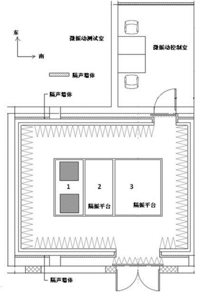
[0027] The spacecraft sound elimination, vibration isolation and micro-vibration laboratory of the present invention is built in the AIT hall of the environmental test, the north and south sides are the vibration test hall, and the west side is the product transportation channel. On the east side are equipment rooms such as vibration table amplifiers and cooling units. The vibration of the shaking table, the movement of people, the vibration generated by equipment transportation and the voice of people speaking will have a great impact on the micro-vibration test...


PUM


Abstract

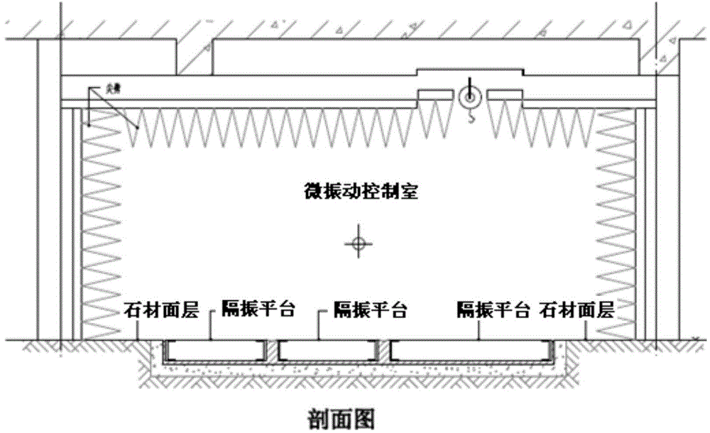
The invention discloses a spacecraft damping vibration isolation micro-vibration test chamber which is divided into a test chamber body and a control chamber body. The test chamber body comprises a room body, vibration isolation platforms, a test device and an auxiliary facility. The room body of the test chamber body is a semi-damping chamber, the floor is a gravity-leveled floor, and a roof and surrounding walls of the test chamber body are provided with wedge absorbers respectively. The center of the floor of the test chamber body is provided with three vibration isolation platforms. The first vibration isolation platform is a single-machine micro-vibration source surrounding test station and is provided with two spacecraft single-machine interference source test platforms. The second vibration isolation platform is a special multi-freedom-degree source surrounding simulation station and is provided with a six-freedom-degree source surrounding simulation system. The third vibration isolation platform is a station for a manned spacecraft single-machine noise source device sound power test and a large-part and small satellite whole micro-vibration test and is provided with a product and micro-vibration test tool and the like. The side face of the test chamber body is provided with a sound isolation door beneficial to going in and going out of tested devices or products. The control chamber body is a conventional spacecraft environmental test chamber.

Description

technical field [0001] The invention belongs to the technical field of spacecraft micro-vibration testing and testing, and in particular relates to a spacecraft sound-elimination, vibration-isolation and micro-vibration laboratory. Background technique [0002] Micro-vibration refers to the high-speed rotation of the rotating parts on the star, the stepping motion of the large-scale controllable component drive mechanism, the ignition of the thruster during the orbit change and capital adjustment, and the disturbance induced by the alternating cold and heat of the large-scale flexible structure when it enters and exits the shadow. Make the star produce a jitter response with a smaller amplitude and higher frequency. Micro-vibration disturbance sources exist in most spacecraft. Due to the small amplitude and high frequency of the micro-vibration dynamics environmental effect, it will not have a significant impact on the product of most spacecraft and is usually ignored. How...

Claims


Application Information

Patent Timeline
IPC IPC(8): E04H1/12E04B1/82G01M7/02
CPCE04B1/82E04H1/12G01M7/02
Inventor 王鹤晏廷飞方贵前武耀杨江刘沫顾菲王磊
Owner BEIJING INST OF SPACECRAFT ENVIRONMENT ENG
Learn More