Online dedusting device of web die-cutting machine
A technology of dust removal device and die-cutting machine, which is applied in the direction of removing smoke and dust, cleaning method using gas flow, metal processing, etc. False positives in quality detection, avoid false positives in detection, and reduce workload
- Summary
- Abstract
- Description
- Claims
- Application Information
AI Technical Summary
Problems solved by technology
Method used
Image
Examples
Embodiment 1
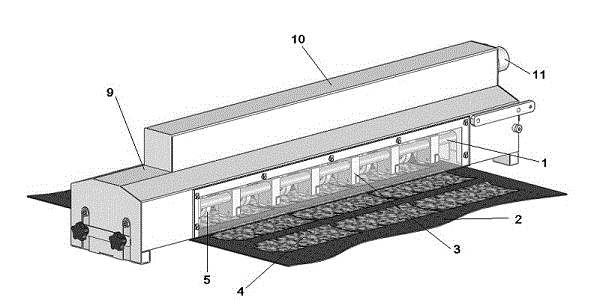
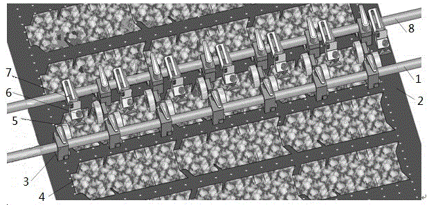
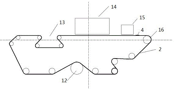
[0024] Such as Figure 1 ~ Figure 3 As shown, several conveying roller shafts 16 are horizontally installed on the frame, and a kind of perforated conveying belt 2 with a wide format and full of small holes is laid on the conveying roller shaft 16, and the conveying roller shaft 16 rotates to drive the perforated conveying belt 2 moves forward, and the product 4 to be dedusted moves forward under the drive of the perforated conveyor belt 2.
[0025] Such as figure 2 As shown, a first shaft 1 is installed in the input direction of the product 4 to be dedusted, on which a row of press wheel frames 3 and its press wheels 5 are installed, and a second shaft 1 is installed in the output direction of the product 4 to be dedusted. Axle 8, on this second root shaft 8, be installed with pinch wheel frame 4 and its pinch wheel 5, air nozzle frame 7 and its air nozzle, pinch wheel frame 3 and its pinch wheel 5 and blowing The mouth frame 7 and its blowing nozzle are closely adjacent t...
Embodiment 2
[0028] With reference to embodiment 1, as figure 2 As shown, the second shaft 8 is designed as a hollow shaft with one end sealed, and a through hole communicated with the blowing nozzle is opened on the blowing nozzle frame 7, and a through hole is opened at a corresponding position on the second shaft 8 to communicate with the blowing nozzle. The through holes on the mouth frame 7 are connected, and the second shaft 8 hollow part and the through hole on the blowing nozzle frame 7 form a positive pressure air pipeline. When the positive pressure air is passed into the hollow of the second shaft 8, positive pressure Compressed air enters the blowing nozzle frame 7 through holes through the second shaft 8 through holes, and then enters the blowing nozzle from the blowing nozzle frame 7 through holes, and the blowing nozzle can blow out strong wind. Other technical elements are the same as in Embodiment 1.
Embodiment 3
[0030] With reference to embodiment 1, as figure 1 As shown, in the casing 9 above the blowing nozzle, a negative pressure cavity box fixed on the frame is designed, the negative pressure cavity box communicates with the exhaust port 11 and the exhaust pipe, and the exhaust pipe is connected with the exhaust pump . After starting the suction pump, the suction pipe still sucks away the dust blown by the blowing nozzle. This kind of design can relax the requirements on the design of the casing, which can be designed as a closed casing or as a mesh or grid-shaped casing. Other technical elements are the same as in Embodiment 1.
PUM
 Abstract
Description
Claims
Application Information
 - R&D
- Intellectual Property
- Life Sciences
- Materials
- Tech Scout
- Unparalleled Data Quality
- Higher Quality Content
- 60% Fewer Hallucinations
Browse by: Latest US Patents, China's latest patents, Technical Efficacy Thesaurus, Application Domain, Technology Topic, Popular Technical Reports.
© 2025 PatSnap. All rights reserved.Legal|Privacy policy|Modern Slavery Act Transparency Statement|Sitemap|About US| Contact US: help@patsnap.com


