
Controller For Machine Tool Including Main Shafts

A technology of control device and spindle motor, which is applied in the direction of AC motor control, control system, program control, etc. It can solve the problems of different acceleration and deceleration conditions of the spindle motor, twisted and damaged workpieces, complex mechanical structures, etc.

Active Publication Date: 2015-03-18
FANUC LTD
View PDF8 Cites 10 Cited by
  • Summary
  • Abstract
  • Description
  • Claims
  • Application Information

AI Technical Summary

Problems solved by technology

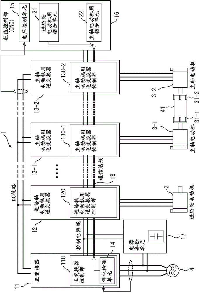
Since the power-off operation is performed independently between the two spindles, there is a problem that the acceleration and deceleration of the spindle motor is different, and the synchronous relationship between the two spindles held by the gripped workpiece is broken, causing workpiece distortion. Failure such as damage or deformation
[0013] In order to avoid the distortion of the workpiece in the machine tool to which such a power failure backup operation is applied, it is also conceivable to further apply the invention described in the above-mentioned Japanese Patent Application Laid-Open No. 2001-105209, but to slow down the movement of the chuck of one spindle when a power failure occurs. It must be done instantaneously, and the mechanical structure to realize it becomes complicated
In addition, when a power failure occurs, control must be performed, and both the power failure backup operation and the slowdown of the chuck operation of one spindle will inevitably complicate the control system.

Method used


Image

  • Controller For Machine Tool Including Main Shafts
  • Controller For Machine Tool Including Main Shafts
  • Controller For Machine Tool Including Main Shafts

Examples


no. 2 example

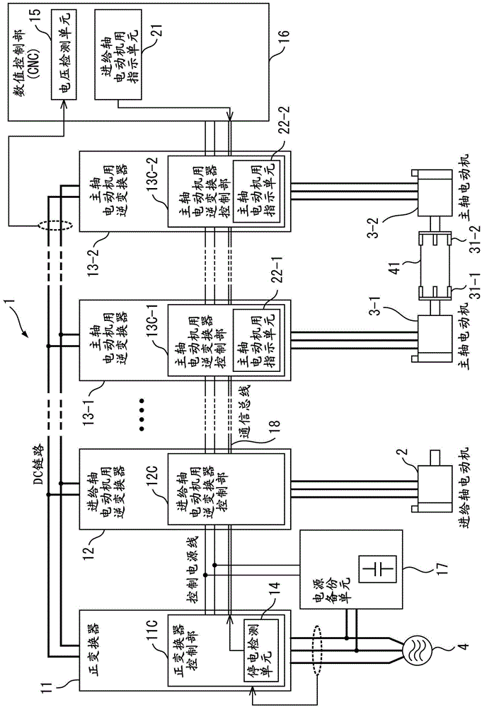
[0070] Regarding the second embodiment, the constituent elements other than the above-mentioned constituent elements are the same as those of the first embodiment, and therefore description thereof will be omitted.

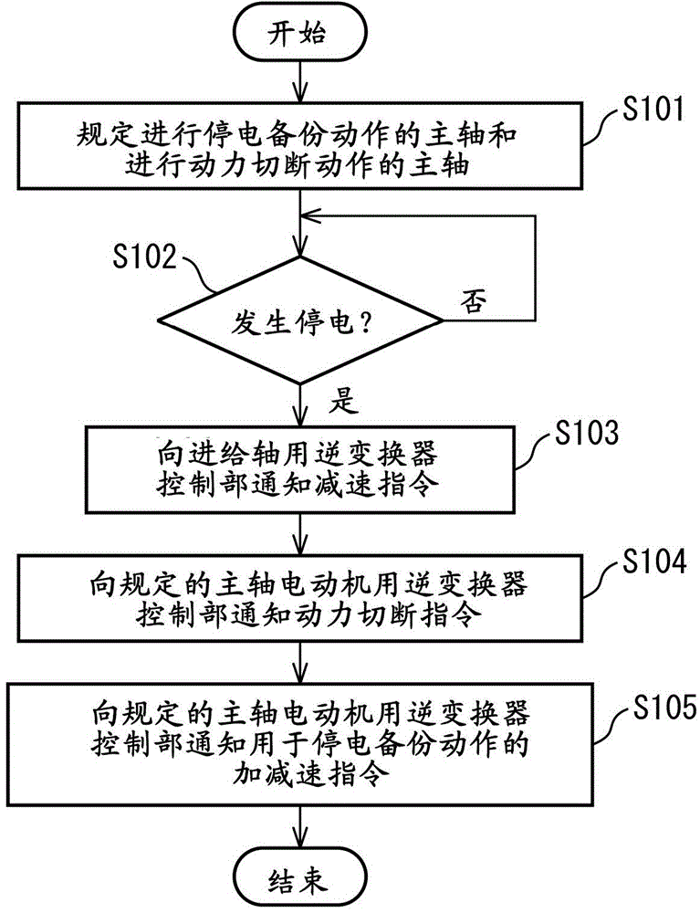
[0071] Figure 5 It is a flowchart showing the flow of operations of the machine tool control device of the second embodiment. Below, the description is in Figure 4 In the example shown, the operation of the control device 1 when a power failure occurs on the side of the AC power supply 4 during machining of the workpiece 41 is shown.

[0072] First, in step S201, in the numerical control unit 16 functioning as a higher-level control unit for the first spindle motor inverter control unit 13C-1 and the second spindle motor inverter control unit 13C-2, In its control program, it is specified as the inverse converter 13-1 for the first spindle motor and the inverse converter for the second spindle motor when a power failure occurs on the side of the AC power suppl...


PUM


Abstract

A controller for a machine tool includes a converter converting AC power on the power supply side to DC power, a feed-shaft motor inverter converting DC power on a DC link side and AC power on a feed shaft motor side, first and second main-shaft-motor inverters converting DC power on the DC link side and AC power on first and second main shaft motors side, a power failure detection unit detecting a power failure on the power supply side, a voltage detection unit detecting a DC link voltage value, a feed-shaft-motor command unit outputting a deceleration command to the feed-shaft-motor inverter upon a power failure, and a main-shaft-motor command unit outputting an acceleration / deceleration command to the first main-shaft-motor inverter in accordance with the DC link voltage value and a power shutoff command to the second-main-shaft-motor inverter upon a power failure.

Description

technical field [0001] The present invention relates to a control device for a machine tool having a feed shaft motor for driving a feed shaft and a spindle motor for driving a spindle, and particularly relates to a machine tool protection during power failure that synchronizes the movements of two spindles via a workpiece being held. control device. Background technique [0002] In machine tools having a feed shaft motor and a spindle motor, most of the spindle motors are used, for example, as a drive source for driving a spindle on which workpieces, tools (various tools) are mounted, and the feed shaft motor is used, for example, as a drive source for driving the spindle. The drive source of the moving feed axis. In such a machine tool motor control device, AC power input from an AC input side is once converted into DC power and then converted into AC power, and the AC power is used as driving power for a motor provided for each drive shaft. In such a machine tool, the m...

Claims


Application Information

Patent Timeline
Patent Type & Authority Applications(China)
IPC IPC(8): H02P27/06
CPCG05B19/4166G05B19/406G05B2219/34434G05B2219/50081G05B2219/50083
Inventor 田岛大辅
Owner FANUC LTD
Learn More