
Detonator delay time tester

A technology of delay time and tester, which is applied in the direction of electrical unknown time interval measurement, devices and instruments for measuring time interval, etc., can solve the problems of high production cost, large safety hazard, cumbersome operation, etc., to increase vibration, avoid damage, The effect of reducing adverse outcomes

Inactive Publication Date: 2015-03-04
GUANGDONG HONGDA BLASTING
View PDF5 Cites 5 Cited by
  • Summary
  • Abstract
  • Description
  • Claims
  • Application Information

AI Technical Summary

Problems solved by technology

[0006] The object of the present invention is to provide a detonator delay time tester with simple structure, convenient operation, safe and accurate testing in order to solve the defects of the above-mentioned prior art such as complex structure, cumbersome operation, high production cost and great safety hazards.

Method used


Image

  • Detonator delay time tester
  • Detonator delay time tester
  • Detonator delay time tester

Examples


Embodiment 1

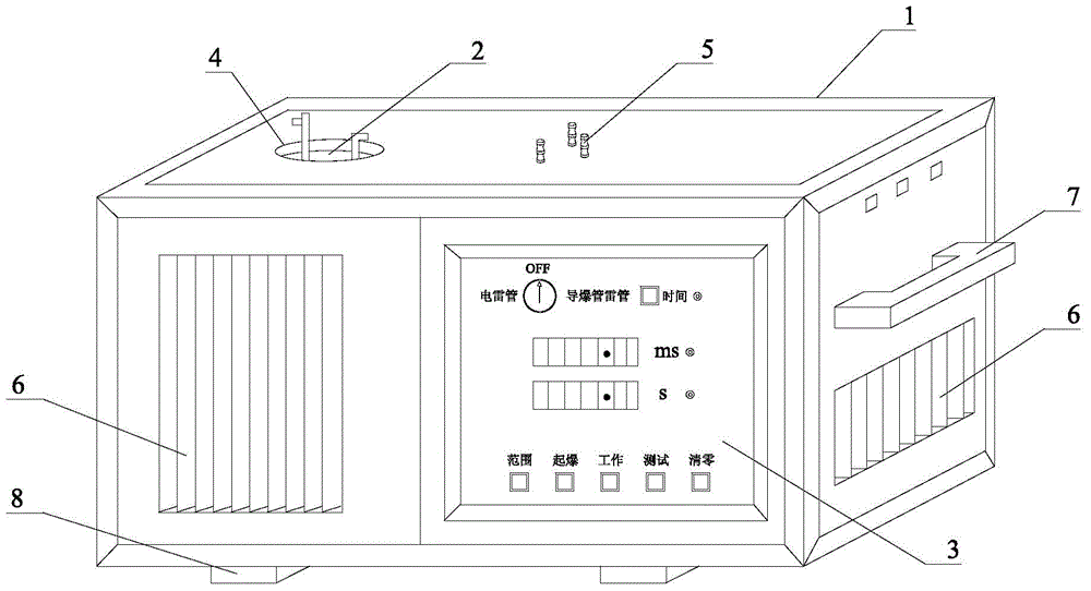
[0044] Such as figure 1 As shown, the detonator delay time tester of the present embodiment includes a tester body 1, an explosion box 2 and a test box 3, the explosion box 2 is arranged in the tester body 1, and the test box 3 is arranged in the tester body 1 Above; the top plate of the tester body 1 is provided with an opening 4 and a terminal 5, and the terminal 5 includes two electric detonator foot wire terminal posts and a nonel detonator detonation firing pin; the tester body The front panel and the side panels of 1 are provided with cooling windows 6, and the side panels of the tester body 1 are also provided with handles 7; the bottom panel of the tester body 1 is provided with bottom wheels 8.

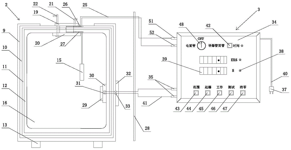
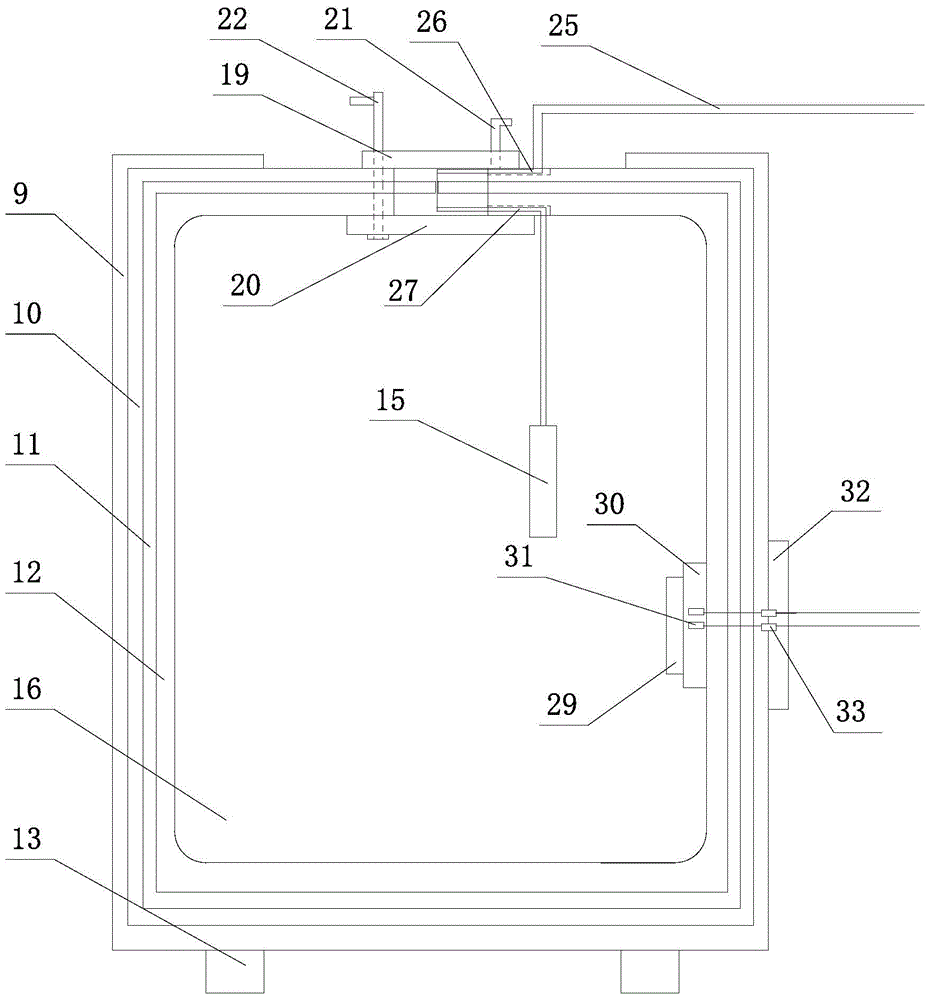
[0045] Such as Figure 1 to Figure 6 As shown, the explosion box 2 includes a box body, a box cover and a sensor system, and the box body sequentially includes a reinforced steel plate 9, an outer layer steel plate 10, a rubber layer 11 and an inner layer steel plate 12 from...

Embodiment 2

[0056] The main features of this embodiment are: the upper opening 14 and the lower opening 17 are circular openings with a diameter of 15 cm. Correspondingly, the length of the gap 18 is consistent with the diameters of the upper opening 14 and the lower opening 17. . All the other are with embodiment 1.

Embodiment 3

[0058] The main feature of this embodiment is: the cross-sectional shape of the first reserved hole 26 and the second reserved hole 27 can also be square, rectangular and other shapes. All the other are with embodiment 1 or 2.


PUM


Abstract

The invention discloses a detonator delay time tester. The detonator delay time tester comprises a tester body, an explosion box arranged inside the tester body and a test box arranged on the tester body, wherein the explosion box comprises a box body, a box cover and a sensing system; a base is arranged at the bottom of the box body; the sensing system is connected with the test box; the box comprises a reinforced steel plate, an outer steel plate, a rubber layer and an inner steel plate which are sequentially arranged from outside to inside; an upper opening is formed in the top of the outer steel plate; an inner chamber used for storing to-be-tested detonators is defined by the encircling of the inner steel plate; a lower opening is formed in the top of the inner steel plate; a box cover comprises an outer box cover, an inner box cover, an outer box cover handle and an inner box cover handle; the outer box cover is arranged at the upper opening; the outer box cover handle is fixedly connected with the outer box cover; the inner box cover is arranged at the lower opening; the inner box cover is fixedly connected with the inner box cover. The detonator delay time tester is simple in structure and convenient to operate, and is capable of safely and accurately testing.

Description

technical field [0001] The invention relates to a tester, in particular to a detonator delay time tester, which belongs to the technical field of detonator testing. Background technique [0002] At present, with the development of industrial technology, delayed detonators have been more and more widely used in engineering blasting, especially in the excavation process of open-pit mines. The blasting large block rate and the reduction of blasting flying stones have played a key role. Delayed detonators are divided into delayed electric detonators, delayed nonel detonators and electronic detonators, and the delay time of electronic detonators is set by the built-in chip of the detonator and the computer system. Yes, its delay time error is small, and it has been widely used in some projects that require high precision in delay time. Delay detonators can be divided into millisecond delay detonators, half-second delay detonators and second delay detonators according to the lengt...

Claims


Application Information

Patent Timeline
Patent Type & Authority Applications(China)
IPC IPC(8): F42C21/00G04F10/00
Inventor 祝云辉郑炳旭李战军伏岩岳本祯刘翼王佩佩
Owner GUANGDONG HONGDA BLASTING
Learn More