Radial-axial magnetic field electromagnetic planetary gear power divider
A technology of power splitter and planetary gear, which is applied in magnetic circuits, electrical components, electromechanical devices, etc., can solve the problems of power output, limited performance, complex structure, etc., and achieve reduced exhaust emissions, simple structure, and small volume. Effect
- Summary
- Abstract
- Description
- Claims
- Application Information
AI Technical Summary
Problems solved by technology
Method used
Image
Examples
specific Embodiment approach 1
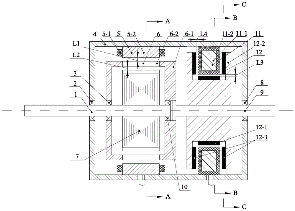
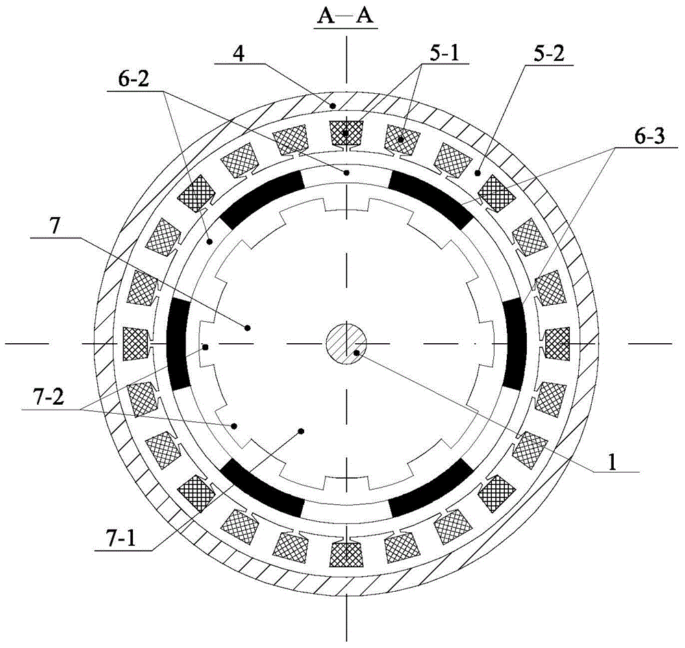
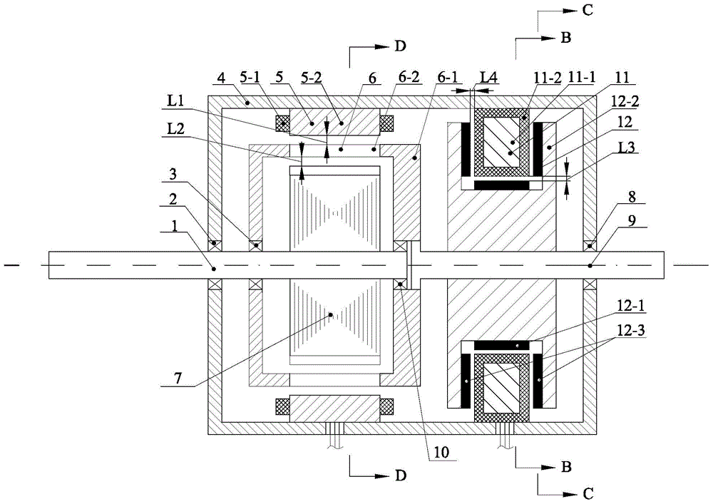
[0035] Specific implementation mode one: the following combination Figure 1-18 Describe this embodiment, the radial-axis radial magnetic field electromagnetic planetary gear power divider in this embodiment is provided with a radial double-rotor motor and a shaft-radial torque regulating motor in parallel in the housing 4, and the radial The dual-rotor motor includes a first stator 5, a first permanent magnet rotor 6, a magnet rotor 7, a magnet rotor output shaft 1 and a permanent magnet rotor output shaft 9, and the shaft radial torque adjustment motor includes a second stator 11 And the second permanent magnet rotor 12, the permanent magnet rotor output shaft 9 is simultaneously used as the rotor shaft of the shaft radial torque regulating motor,
[0036] The second stator 11 of the shaft radial torque regulating motor is fixed on the inner circular surface of the housing 4, the second permanent magnet rotor 12 is fixed on the permanent magnet rotor output shaft 9, the seco...
specific Embodiment approach 2
[0046] Specific implementation mode two: the following combination figure 1 , figure 2 , Figure 7 ~ Figure 18 Describe this embodiment, this embodiment will further explain Embodiment 1, the first permanent magnet rotor 6 includes a rotor bracket 6-1, n first permanent magnet units 6-2 and n second permanent magnet units 6-3, The rotor bracket 6-1 evenly distributes the first permanent magnet units 6-2 and the second permanent magnet units 6-3 in a staggered manner along the circumferential direction, the magnetization directions of the n first permanent magnet units 6-2 are the same, and the n second permanent magnet units The magnetization directions of the magnet units 6-3 are the same, and the magnetization directions of the first permanent magnet unit 6-2 and the second permanent magnet unit 6-3 are opposite.
[0047] The magnetization direction of the first permanent magnet unit 6-2 is radial magnetization or radial parallel magnetization.
[0048] The magnetization...
specific Embodiment approach 3
[0089] Specific implementation mode three: the following combination image 3 and Figure 4 Describe this embodiment, this embodiment will further illustrate the first embodiment, the first permanent magnet rotor 6 includes a rotor bracket 6-1, n first permanent magnet units 6-2 and n permanent magnet rotor cores 6-4, the rotor The support 6-1 evenly distributes the first permanent magnet units 6-2 and the permanent magnet rotor cores 6-4 in a staggered manner along the circumferential direction, and the magnetization directions of the n first permanent magnet units 6-2 are the same.
[0090] The magnetization direction of the first permanent magnet unit 6-2 is radial magnetization or radial parallel magnetization.
[0091] The permanent magnet rotor core 6-4 is a silicon steel sheet or solid iron.
[0092] The advantage of this embodiment is that under the permanent magnetic field with the same number of pole pairs, half of the amount of permanent magnets is saved.
PUM
 Abstract
Description
Claims
Application Information
 - R&D
- Intellectual Property
- Life Sciences
- Materials
- Tech Scout
- Unparalleled Data Quality
- Higher Quality Content
- 60% Fewer Hallucinations
Browse by: Latest US Patents, China's latest patents, Technical Efficacy Thesaurus, Application Domain, Technology Topic, Popular Technical Reports.
© 2025 PatSnap. All rights reserved.Legal|Privacy policy|Modern Slavery Act Transparency Statement|Sitemap|About US| Contact US: help@patsnap.com


