Integrated detection structure of vortex flowmeter

A vortex flowmeter and integrated detection technology, which is applied in the direction of volume/mass flow, volume change compensation/correction device, etc. by detecting the dynamic effect and mechanical effect of fluid flow, can solve the problems of increasing fluid leakage and increasing processing Problems such as process, time, and drilling accuracy are difficult to grasp, so as to achieve the effect of simplifying structural design, preventing mutual interference, and ensuring normal and stable operation

Inactive Publication Date: 2015-02-25
ZHONGHUAN TIG
View PDF7 Cites 2 Cited by
  • Summary
  • Abstract
  • Description
  • Claims
  • Application Information

AI Technical Summary

Problems solved by technology

[0003] Commonly used vortex flowmeters are mostly used to measure liquid flow. If you need to measure gas, you need to measure temperature and pressure while measuring the flow to supplement the deviation of density on gas flow; existing gas vortex flowmeters need to be Additional pressure-taking holes and temperature-taking holes are set on the meter body or pipeline, and pressure-taking and temperature-taking devices are welded, such as Figure 4 , Figure 5 As shown, on the one hand, it is difficult to grasp the drilling accuracy, which increases the processing procedures and time, and on the other hand, the structure of the vortex flowmeter becomes more complicated, especially in the process of increasing the hidden danger of fluid leakage.

Method used


Image

  • Integrated detection structure of vortex flowmeter
  • Integrated detection structure of vortex flowmeter
  • Integrated detection structure of vortex flowmeter

Examples


Embodiment Construction

[0012] Below in conjunction with accompanying drawing and embodiment the present invention will be further described:

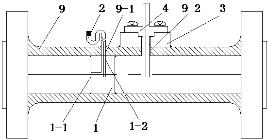
[0013] Such as Figure 1 to Figure 3 As shown, an integrated detection structure of a vortex flowmeter includes a vortex flowmeter casing 9 connected to a pipeline, and also includes a sounding body 1, an S-shaped tube 2, a probe fixing member 3, a probe 4, a temperature connecting line 5, Flow detector 6 temperature detector 7, filler 8.

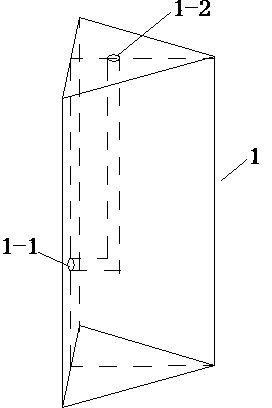
[0014] The sounding body 1 is a triangular shape, with an air inlet 1-1 on the side wall of the sounding body 1, and an air outlet 1-2 on the top of the sounding body 1, and the air outlet 1-2 is located at the center of gravity of the top end surface of the sounding body 1 , the air inlet 1-1 and the air outlet 1-2 form an L-shaped pressure guiding channel.

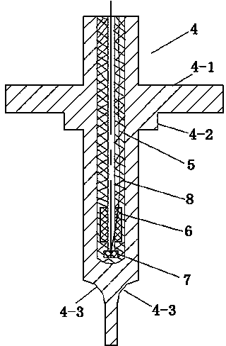
[0015] The probe 4 is a cylindrical body with an inner cavity, the upper end of the probe 4 is provided with a circular flange 4-1, the lower part of the circular ...


PUM


Abstract

The invention relates to an integrated detection structure of a vortex flowmeter. A temperature detector is fixed to the bottom of a flow detector, the flow detector and a temperature connection line connected with the temperature detector are encapsulated in a probe cavity through filler, a probe fixing element is fixed to the wall of a shell of the vortex flowmeter, the lower end of the probe sequentially penetrates through a hole of the probe fixing element, the probe hole is formed in a pipeline of the shell of the vortex flowmeter, a round flange plate at the upper probe is fixedly connected with the probe fixing element, a sound making body is fixed in the shell of the vortex flowmeter, an air outlet of the sound making body is communicated with a channel hole of the shell of the vortex flowmeter, and an S-shaped tube is fixed to the channel hole of the shell of the vortex flowmeter. The integrated detection structure has the advantages that simultaneous measuring of temperature, pressure and flow points is achieved; meanwhile, the sound making body and the probe are effectively protected in a sealed mode by filling epoxy resin or inorganic glue, the functions of isolation, moisture resistance and connection line interference prevention are achieved, and normal stable operation of a sensor is further guaranteed.

Description

technical field [0001] The invention relates to an integrated detection structure of a vortex flowmeter. Background technique [0002] The vortex flowmeter in the prior art is a fluid oscillating instrument developed according to the "Karman vortex street". The triangular column sounding body is used to separate the Karman vortex. The frequency of vortex separation is proportional to the flow rate, and the vortex frequency is detected by piezoelectric ceramics. , and converted into an alternating signal, and then measured volume flow and instantaneous flow. [0003] Commonly used vortex flowmeters are mostly used to measure liquid flow. If you need to measure gas, you need to measure temperature and pressure while measuring the flow to supplement the deviation of density on gas flow; existing gas vortex flowmeters need to be Additional pressure-taking holes and temperature-taking holes are set on the meter body or pipeline, and pressure-taking and temperature-taking devices...

Claims


Application Information

Patent Timeline
Patent Type & Authority Applications(China)
IPC IPC(8): G01F1/32G01F15/02
Inventor 朱玉兰郑晓林杨彬梁玉堂王质琳
Owner ZHONGHUAN TIG
Why Eureka
Try Eureka