


Quick Research
Generate reliable direction feasibility study reports for your R&D in just a few steps.

Technical Q&A
Discover and master advanced knowledge NOW. Basics, ideas, possibilities, all at once.

Find Solutions
As an expert in R&D theories, this can generate solutions to your technical problems instantly.

Evaluate Feasibility
Analyze your overall solution with one click, know your potential R&D risks in advance.

Monitor Landscape
Get weekly tech updates, stay abreast of the latest tech innovations and key insights.
Gas turbine with improved part load emissions behavior
A gas turbine and turbine technology, which is used in gas turbine devices, fuel control of turbine/propulsion devices, exhaust devices, etc., can solve problems such as high CO emissions, and achieve the effects of low CO emissions and reduced CO2 emissions.
- Summary
- Abstract
- Description
- Claims
- Application Information
AI Technical Summary
Problems solved by technology
Method used
Image


Examples
Embodiment Construction
[0080] figure 1 A sequential combustion gas turbine that can be used to practice the methods described herein is shown. The gas turbine comprises a compressor 1 , a first combustor 4 , a first turbine 7 , a second combustor 15 and a second turbine 12 . Typically, it comprises a generator 19 coupled to the shaft 18 of the gas turbine at the cold end of the gas turbine, that is to say at the compressor 1 .
[0081] Fuel, gas or oil is introduced into the first burner 4 via a fuel feed 5 , mixed with air, which is compressed in the compressor 1 , and combusted. The hot gas 6 is partially expanded in the subsequent first turbine 7, performing the work.
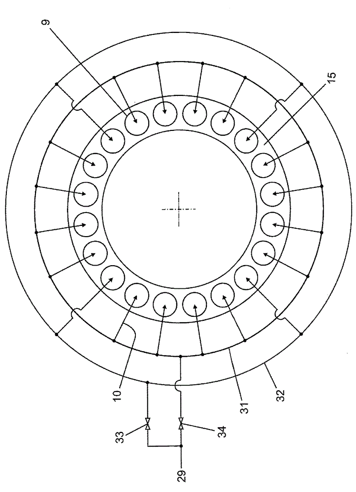
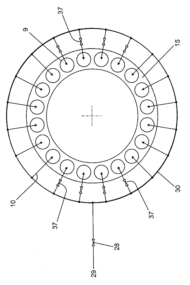
[0082] As soon as the second burner is running due to increased load, additional fuel is added to the partially expanded gas 8 in the burner 9 of the second burner 15 via the fuel feed 10 and in the second burner 15 combustion. The hot gas 11 is expanded in the subsequent second turbine 12, performing the work. The exhaust ga...
PUM
 Abstract
Description
Claims
Application Information
 - R&D Engineer
- R&D Manager
- IP Professional
- Industry Leading Data Capabilities
- Powerful AI technology
- Patent DNA Extraction
Browse by: Latest US Patents, China's latest patents, Technical Efficacy Thesaurus, Application Domain, Technology Topic, Popular Technical Reports.
© 2024 PatSnap. All rights reserved.Legal|Privacy policy|Modern Slavery Act Transparency Statement|Sitemap|About US| Contact US: help@patsnap.com