Hydraulic feeding numerical control press

A CNC punching and feeding technology, which is applied in metal processing equipment, feeding devices, manufacturing tools, etc., can solve the problems of high punching processing cost of large workpieces, positioning or feeding device punching, etc., to solve the processing of positioning and feeding. Problems, low cost, good versatility

Inactive Publication Date: 2015-02-25
ANHUI SANLI MACHINE TOOL MFG
View PDF1 Cites 5 Cited by
  • Summary
  • Abstract
  • Description
  • Claims
  • Application Information

AI Technical Summary

Problems solved by technology

[0005] Aiming at the problems existing in the prior art that the punching cost of large workpieces is high and that the punching machine is easy to damage the positioning or feeding device in the punching machine when processing the workpiece tailings, the present invention provides a numerically controlled punching machine with hydraulic feeding

Method used


Image

  • Hydraulic feeding numerical control press

Examples


Embodiment 1

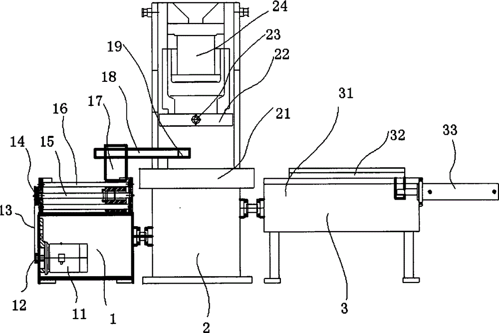
[0034] Such as figure 1 As shown, a hydraulic feeding CNC punch press of this embodiment includes a positioning part 1 and a blanking part 2, and also includes a hydraulic feeding part 3; The left and right ends are fixedly connected respectively.

[0035] The blanking part 2 includes a workbench 21 , a slider 22 , a punching die 23 and a press 24 . The workbench 21 is located in the middle of the blanking part 2 . The slide block 22 , the punching die 23 and the press machine 24 form a whole and are vertically fixed above the workbench 21 with a bracket; the slide block 22 is fixed at the lower end of the press machine 24 . The punching die 23 is fixed on the lower surface of the middle part of the slider 22 ; the hydraulic feeding part 3 includes a feeding frame 31 , a feeding slider 32 and a feeding cylinder 33 . The feeding slider 32 is located on the upper surface of the feeding frame 31; the feeding cylinder 33 is fixed on the right side of the feeding frame 31; the f...

Embodiment 2

[0044] A kind of hydraulic feeding CNC punching machine of this embodiment, its basic structure is the same as that of Embodiment 1, the difference is that: there are 4 punches on the punching die 23; the right end of the retaining finger 18 is higher than the Workbench 21 upper surface 3cm.

[0045] A kind of hydraulic feed numerical control punching machine of this embodiment, its concrete processing process to the I-beam is the same as embodiment 1, the difference is: this embodiment is suitable for processing the I-beam with higher height, and the press 24 drives the punching die 23 vertical drops can punch down 4 holes of every row of the I-beam.


PUM


Abstract

The invention discloses a hydraulic feeding numerical control press, and belongs to the field of machine tool equipment. The hydraulic feeding numerical control press comprises a positioning component, a blanking component and a hydraulic feeding component. The positioning component and the hydraulic feeding component are fixedly connected with the left end and the right end of the blanking component respectively. The positioning component comprises a servo motor, a small belt wheel, a synchronous belt, a large belt wheel, a ball screw, a cylindrical guide rail, a sliding base, a blocking finger and an approaching switch. The blanking component comprises a work table, a sliding block, a punching die and a press machine. The hydraulic feeding component comprises a feeding rack, a feeding sliding block and a feeding oil cylinder. The upper surface of the work table and the upper surface of the feeding sliding block are on the same horizontal line. The right end of the blocking finger is higher than the upper surface of the work table. The vertical line of a plunger chip of the punching die is parallel with the plane of the right end of the blocking finger. A workpiece does not make contact with the positioning component or the feeding component during positioning or feeding and cannot be worn, precision is high, stability is good, and the machining problem of positioning and supplying the large workpiece on the press is solved.

Description

technical field [0001] The invention relates to the field of machine tool equipment, in particular to a numerically controlled punching machine with hydraulic feeding. Background technique [0002] At present, in the traditional processing technology, a drilling machine is used to drill holes in the workpiece. During the processing, the general workpiece is relatively heavy, and it is difficult to locate the workpiece when moving. Therefore, the processing efficiency is extremely low, and the distance between holes is not easy to ensure. If mechanical servo feeding is adopted, because the workpiece is relatively heavy, the requirements for the power of the servo motor and the diameter of the screw are very high, and the cost is correspondingly high. [0003] Chinese patent application number: 201010554105.3, application date: 2010.11.19, invention name: CNC punching machine. The invention discloses a numerically controlled punching machine, which includes a body and a work...

Claims


Application Information

Patent Timeline
Patent Type & Authority Applications(China)
IPC IPC(8): B21D28/24B21D43/02
CPCB21D28/24B21D43/02
Inventor 陈道宝张正兵陈斌斌
Owner ANHUI SANLI MACHINE TOOL MFG
Why Eureka
Try Eureka