Visualized plane sand packing model for oil displacement experiments
A flat, sand-filling technology, applied in the direction of mining fluid, wellbore/well components, earthwork drilling and production, etc., can solve the problems of high permeability of sand filling, poor sealing, poor sealing between face plate and sand inclusion, etc., and achieve a high degree of visualization , good sealing effect
- Summary
- Abstract
- Description
- Claims
- Application Information
AI Technical Summary
Problems solved by technology
Method used
Image
Examples
Embodiment 1
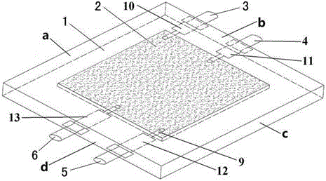
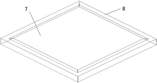
[0027] Specifically, the visualized planar sand filling model used for oil displacement experiments includes a base plate 1 and a panel 8 arranged on the top of the base plate 1. Two square acrylic plates of 100mm×100mm×25mm are selected as the base plate 1 and the panel 8 respectively. The base plate 1 and the panel 8 are bonded and connected by carpentry clamps. In order to solve the problem of poor sealing performance between the bottom plate 1 and the sand filling surface in the plane sand filling model, a square concave cavity that can accommodate fillers is set in the center of the bottom plate 1. Groove 2, filled with fine quartz sand and coarse quartz sand, the depth of the square groove 2 is 5mm, the side length is 50~80mm, and the first screw thread is arranged clockwise on the side b of the square groove 2 hole 10 and the second threaded hole 11, the third threaded hole 12 and the fourth threaded hole 13 are arranged clockwise on the opposite side d surface of the si...
Embodiment 2
[0030] On the basis of Example 1, further, in order to make the bond between the bottom plate 1 and the panel 8 more firm, choose to bond the bottom plate 1 and the panel 8 through silicon rubber 7, the first threaded hole 10, the second threaded hole 11 , The specific positions of the third threaded hole 12 and the fourth threaded hole 13 are that the second threaded hole 11 and the fourth threaded hole 13 are arranged oppositely, and the first threaded hole 10 and the third threaded hole 12 are respectively arranged in the square groove 2 At the end of the side and the end of the opposite side, the second threaded hole 11 and the fourth threaded hole 13 are respectively arranged at the midpoint of the side of the square groove 2 and the midpoint of the opposite side; it should be noted that the base plate 1 and the The panels 8 are all square acrylic plates, and the two are connected by silicon rubber.
Embodiment 3
[0032] On the basis of embodiment 1 and embodiment 2, a kind of sand filling method utilizing this visual plane sand filling model for oil displacement experiment, comprises the steps:
[0033] a. Select two square acrylic plates of 100mm×100mm×25mm as the bottom plate 1 and the panel 8 respectively;
[0034] b. Make a square groove 2 of 65mm×65mm×5mm at the center of the bottom plate 1 through micromachining technology;
[0035] c. On the b surface and d surface of the base plate 1, drill and tap through micromachining technology (the method of processing a hole on a solid material body with a drill bit is called drilling; use a tap to process an internal thread on the inner surface of a cylindrical hole The operation is called tapping), and the first threaded hole 10, the second threaded hole 10, the The second threaded hole 11, the third threaded hole 12, the fourth threaded hole 13, and then the water flow channel 9 is processed on the bottom plate 1 by micromachining tec...
PUM
 Abstract
Description
Claims
Application Information
 - R&D Engineer
- R&D Manager
- IP Professional
- Industry Leading Data Capabilities
- Powerful AI technology
- Patent DNA Extraction
Browse by: Latest US Patents, China's latest patents, Technical Efficacy Thesaurus, Application Domain, Technology Topic, Popular Technical Reports.
© 2024 PatSnap. All rights reserved.Legal|Privacy policy|Modern Slavery Act Transparency Statement|Sitemap|About US| Contact US: help@patsnap.com


