Plasma pyrolytic coal-derived acetylene reactor

A plasma and pyrolysis reaction technology, applied in the field of reactors, can solve the problems of difficult uniform temperature in the reaction zone, large heat loss in the reactor, and generation of oxidizing atmosphere, so as to improve reaction efficiency, increase acetylene yield, and reduce heat energy loss Effect

Active Publication Date: 2015-02-18
合肥碳艺科技有限公司
View PDF7 Cites 8 Cited by
  • Summary
  • Abstract
  • Description
  • Claims
  • Application Information

AI Technical Summary

Problems solved by technology

However, for larger particles or particles moving toward the wall at a higher speed, the gas film cannot prevent them from colliding with the reactor wall, and this method requires energy consumption and / or generates an oxidizing atmosphere, which is not conducive to the formation of acetylene
Chinese patent CN200820176634.2 also adopts a method similar to the above, the difference is that there are tangential air holes around the entire wall of the plasma pulverized coal pyrolysis reactor, and fluid is introduced through the air holes, and a layer is formed by rotating and flowing on the surface of the reactor. The protective film prevents the deposition of high-temperature carbon powder particles on the wall of the reactor. However, the physical protection effect of the gas film is also difficult to meet the requirements. If oxidants or steam are used, the generation of acetylene will be affected.
[0006] Therefore, there are problems in the prior art that the heat loss of the reactor is too large and the temperature in the reaction zone is difficult to be uniform, thereby reducing the reaction efficiency and the yield of acetylene. The problem of coking on the wall of the reactor, however, additional energy consumption is generated in the application process, and the prior art cannot completely solve the problem of coking on the wall of the reactor

Method used


Image

  • Plasma pyrolytic coal-derived acetylene reactor
  • Plasma pyrolytic coal-derived acetylene reactor

Examples


Embodiment Construction

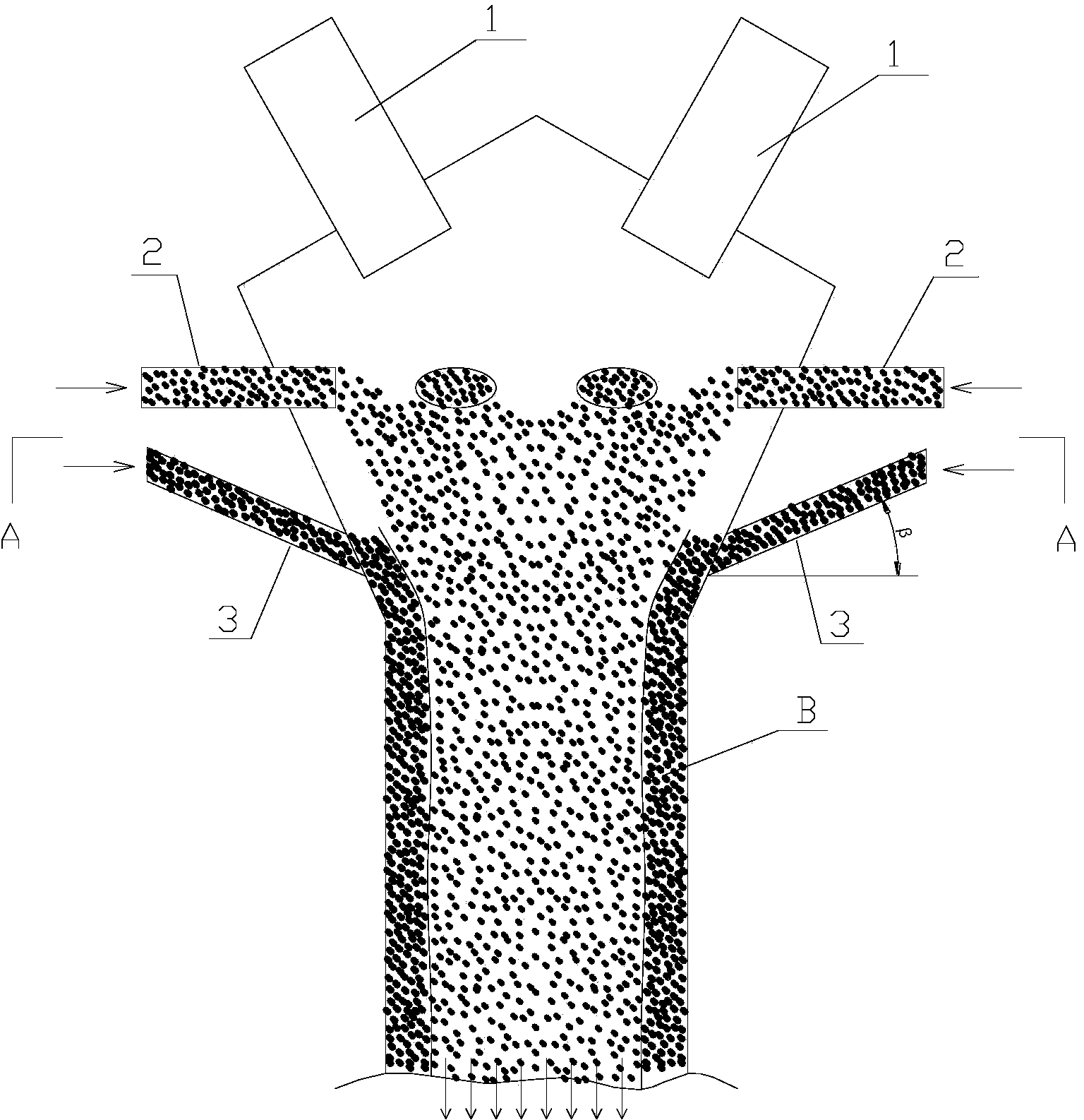
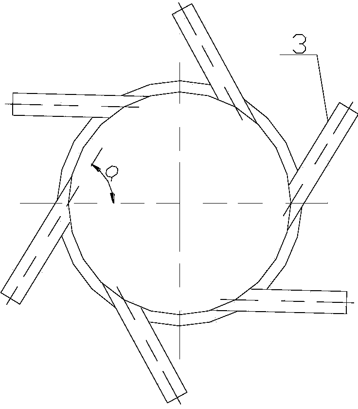
[0022] Such as Figure 1-Figure 2 as shown, figure 1 It is a structural schematic diagram of a plasma pyrolysis coal-to-acetylene reactor proposed by the present invention, figure 2 for figure 1 Middle A-A sectional view.

[0023] refer to Figure 1-2 , a plasma pyrolysis coal-to-acetylene reactor proposed by the present invention, a plurality of arc plasma generators 1 and a plurality of pulverized coal input nozzles 2 are installed above the reactor, and the high-temperature ionized gas generated by the arc plasma generator 1 It is mixed with the pulverized coal ejected from the pulverized coal input nozzle 2 to form a pulverized coal gas mixed reactant, and then flows down into the pulverized coal heating pyrolysis reaction section below the reactor, where the pulverized coal heats up the temperature rising gas rapidly in the pulverized coal heating pyrolysis reaction section and generate acetylene; multiple solid powder nozzles 3 are installed on the reactor, and the ...


PUM

PropertyMeasurementUnit
melting pointaaaaaaaaaa

Abstract

The invention discloses a plasma pyrolytic coal-derived acetylene reactor. A plurality of plasma generators and a plurality of coal powder input nozzles are mounted on the reactor, and high-temperature ionized gas produced by the plasma generators and coal powder sprayed out by the coal powder input nozzles are mixed to form coal powder and gas mixed reactant in the reactor; a plurality of solid powder spray nozzles are mounted below the coal powder input nozzles on the wall of the reactor, a flowing solid powder isolating layer is formed by solid powder which is sprayed out by a plurality of solid powder spray nozzles on the inner wall of the reactor, the flowing solid powder isolating layer is encircled to form a pyrolytic reaction passage, and the axial flow direction of the flowing solid powder isolating layer is consistent with the flow direction of the coal powder and gas mixed reactant. Through use of the plasma pyrolytic coal-derived acetylene reactor disclosed by the invention, the heat energy depletion is reduced, the reaction efficiency and the acetylene recovery are improved, the coking problem of the wall of the reactor is completely solved, and the wall of the reactor can be protected from being over burned.

Description

technical field [0001] The invention relates to the technical field of reactors, in particular to a plasma pyrolysis coal-to-acetylene reactor. Background technique [0002] Using thermal plasma or other high-temperature and high-energy media to rapidly pyrolyze coal to acetylene is a short-flow, high-efficiency, and low-emission acetylene production process. Due to the characteristics of high temperature and high enthalpy of plasma, the volume of the reactor for plasma pyrolysis of pulverized coal to acetylene is small, which easily causes the wall of the reactor to be burned; at the same time, due to the inhomogeneity of the temperature in the reaction zone, the reaction efficiency is low and causes The heating process of pulverized coal is uneven, and some high-temperature pulverized coal particles that have not been completely pyrolyzed inevitably deposit and coke on the wall of the reactor, blocking the reactor and making it difficult to continue the reaction. [0003]...

Claims


Application Information

Patent Timeline
Patent Type & Authority Applications(China)
IPC IPC(8): C07C11/24C07C1/00
Inventor 夏维东王城张晓宁夏维珞陈瑭廖梦然
Owner 合肥碳艺科技有限公司
Why Eureka
Try Eureka