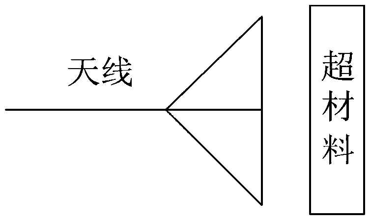
Metamaterials and Antennas
A metamaterial and antenna technology, applied in the field of communication, can solve problems such as difficult implementation, and achieve the effect of reducing side lobes and improving directivity coefficients
- Summary
- Abstract
- Description
- Claims
- Application Information
AI Technical Summary
Problems solved by technology
Method used
Image

Examples
example 4
[0091] Example 4 is mainly to adjust the single main lobe, increase the main lobe level, and reduce the half-beam angle.
[0092] The same pair of in-phase line source arrays work at 1.7GHz, the length of the line source is 529mm, and the normalized pattern is as follows Figure 17 , 18 As shown, the HPBW (Half Power Beam Width) is 17.29°. After the metamaterial with a thickness of D=20mm and the same length as the line source reflector is installed in front of the line source array and 104mm away from the line source reflector, the normalized direction diagram is as follows Figure 16 , 17 As shown, the HPBW is 16.27°, the half-beam angle is significantly reduced, and the directivity of the main lobe of the antenna is stronger.
[0093] The distribution mode of the refractive index and the arrangement mode of the conductive geometric structure inside the second sub-component sheet are:
[0094] The main lobe direction of the antenna is the z direction (radiation direction...
example 5
[0102] Example 5 is mainly to realize the adjustment of the side lobe (reduce the side lobe level):
[0103] The same pair of in-phase line source arrays work at 10GHz, the length of the line source is 270mm, and the normalized pattern is as follows Figure 21 shown. After adding a metamaterial with a thickness of D=3mm and the same length as the line source reflector at the front of the line source array and 15mm away from the line source reflector, the normalized direction diagram is as follows Figure 21 As shown, the side lobe level is obviously suppressed, and the stronger the anti-interference ability of the antenna is.
[0104] The adjustment of the amplitude distribution is achieved by controlling the losses throughout the material, Figure 22 Displays the distribution of the loss tangent (dielectric loss or magnetic loss) on the longitudinal section of the metamaterial. The law of the loss distribution on the longitudinal section is: the loss at the center is small,...
example 6
[0106] Example 6 is mainly to combine amplitude modulation and phase modulation to realize multi-beam adjustment through amplitude and phase weighting materials.
[0107] The working frequency of the array antenna is 3.3GHz, and the height of the aperture surface is 1.1m. Each beam pattern is as follows Figure 23 As shown in the figure, the negative angle in the figure is the beam hitting the ground; after installing a metamaterial with a thickness of D=30mm and the same height as the array antenna at 27mm in front of the array antenna (the distance from the reflector), each beam has been improved (see Figure 24 ), the ground-hitting sidelobe level is significantly suppressed, and the anti-interference ability of the antenna is enhanced.
[0108] The main lobe direction of the antenna is the z direction (radiation direction), the front surface of the metamaterial is the x-y plane, where the vertical direction is y (the center position of the metamaterial is marked as y=0 pos...
PUM
 Abstract
Description
Claims
Application Information
 - R&D
- Intellectual Property
- Life Sciences
- Materials
- Tech Scout
- Unparalleled Data Quality
- Higher Quality Content
- 60% Fewer Hallucinations
Browse by: Latest US Patents, China's latest patents, Technical Efficacy Thesaurus, Application Domain, Technology Topic, Popular Technical Reports.
© 2025 PatSnap. All rights reserved.Legal|Privacy policy|Modern Slavery Act Transparency Statement|Sitemap|About US| Contact US: help@patsnap.com