High-gain low-sidelobe narrow-beam heart-shaped array antenna

An array antenna, low sidelobe technology, applied in antennas, antenna arrays, waveguide horns, etc., can solve the problems of complex and uneconomical feeding systems, and achieve improved directivity coefficient, improved stability, improved operating distance and resolution. rate effect

Inactive Publication Date: 2015-05-13
UNIV OF ELECTRONICS SCI & TECH OF CHINA
View PDF6 Cites 0 Cited by
  • Summary
  • Abstract
  • Description
  • Claims
  • Application Information

AI Technical Summary

Problems solved by technology

This is not only uneconomical, but also makes the feed system more complicated

Method used


Image

  • High-gain low-sidelobe narrow-beam heart-shaped array antenna
  • High-gain low-sidelobe narrow-beam heart-shaped array antenna
  • High-gain low-sidelobe narrow-beam heart-shaped array antenna

Examples


Embodiment Construction

[0024] The present invention will be further described below in conjunction with the accompanying drawings and specific embodiments.

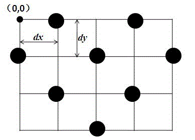
[0025] combine figure 1 As shown, the array consists of 8 array elements. The array layout adopts a triangular grid arrangement, starting from the upper left corner (0, 0), and (m, n) is the grid point at the intersection of the mth row and the nth column. Radiation elements are placed on the grid points where m+n is an odd number, but not placed on the grid points where m+n is an even number. At the same time, starting from the second row, the number of array elements in each row decreases successively, and finally forms Heart shaped structure. The horizontal spacing of the array elements is dx=4mm, and the vertical spacing dy=5mm. The spacing is determined by the minimum working wavelength λ. This design can improve the directivity coefficient of the array, realize the high gain, low sidelobe, and narrow beam characteristics of the array, ...


PUM


Abstract

The invention discloses a high-gain low-sidelobe narrow-beam heart-shaped array antenna which comprises array elements and relates to the technical field of antennas. The array element structure utilizes the design idea of a horn antenna and is integrated into LTCC (Low Temperature Co Fired Ceramic); an array arrangement mode adopts a triangular lattice arrangement mode; the top left corner of an array is marked into (0,0) at the beginning; (m, n) represents a grid point at the junction of an mth row and an nth line; the array elements are arranged on the grid points where the sum of m and n is an odd number; and starting from the second row of the array, the number of the array elements on each row is sequentially reduced to form a heart-shaped structure. According to the invention, due to adoption of the heart-shaped array arrangement mode, the directivity factor of the array can be improved and the characteristics of high gain, low sidelobe and narrow beam (which is represented into a product of 3dB beam widths of an E plane and an H plane) are realized, so that the operating distance and resolution of the antenna array are improved; and the high-gain low-sidelobe narrow-beam heart-shaped array antenna can be applied to aspects of radars, communication systems and the like, such as aircraft, ships, vehicle-mounted devices, and fixed or movable terminal equipment for wireless communication.

Description

technical field [0001] The invention relates to the technical field of antennas, in particular to a cardioid array antenna with high gain, low side lobe and narrow beam. Background technique [0002] At present, the rapid development of wireless communication systems has higher and higher requirements for antennas. For example, radar antennas generally require strong directivity, high gain, low side lobe level, and narrow beams. The beams can realize electrical scanning and other special indicators. A single antenna often fails to meet the predetermined requirements, which requires multiple antennas to be combined. Work together to form an array antenna and jointly achieve a predetermined target. An array antenna is a form of antenna commonly used in modern radar and communication systems. [0003] In the design of array antenna, gain, side lobe level and beam width are important performance indicators. A high gain will directly increase the operating distance; while the ...

Claims


Application Information

Patent Timeline
Patent Type & Authority Patents(China)
IPC IPC(8): H01Q13/02H01Q21/00
Inventor 李家林王心洋王秉中
Owner UNIV OF ELECTRONICS SCI & TECH OF CHINA
Why Eureka
Try Eureka