antenna array

An antenna array and array element technology is applied in the field of small super-directional wide-zero high-frequency receiving antenna arrays, which can solve the problems of receiving array complexity and cost increase.

Active Publication Date: 2016-05-25
哈尔滨工大雷信科技有限公司
View PDF2 Cites 0 Cited by
  • Summary
  • Abstract
  • Description
  • Claims
  • Application Information

AI Technical Summary

Problems solved by technology

[0003] Achieving this with a conventional array approach would lead to a dramatic increase in the complexity and cost of the receiving array

Method used


Image

  • antenna array
  • antenna array
  • antenna array

Examples


Embodiment Construction

[0022] The making and using of various embodiments of the invention are discussed in detail below. It should be appreciated, however, that the present invention provides many applicable concepts that can be implemented in a wide variety of specific contexts. The specific embodiments discussed are merely illustrative of specific ways to make and use the invention, and do not limit the scope of the invention.

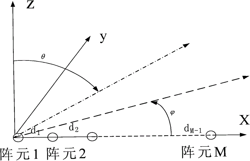
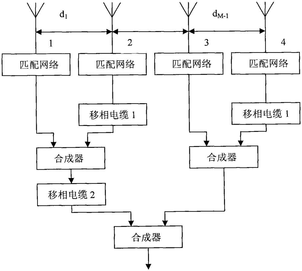
[0023] According to the characteristic that the external noise in the high-frequency band is dominant, the present invention aims at the existing high-frequency over-the-horizon radar and the receiving antenna array of the high-frequency band communication receiving system, which have wide horizontal plane and vertical plane patterns, small directivity coefficients, and poor anti-interference ability and other problems, a new array design method is proposed, which can be used for the design of end-fire arrays in high-frequency bands. Compared with arrays designed by conve...


PUM


Abstract

The invention discloses a high-frequency receiving antenna array which comprises M array elements, the array elements can be arranged with an equal interval and also different intervals, intervals between every two array elements are respectively from d1, d2 to dM-1, and relationships among the array elements is di=dM-i, di=di+2, M=2N, wherein i is a serial number of the interval between every two array elements of the M array elements and smaller than M / 2, N is a positive interger, and the length of the array is determined by the minimum working wavelength gamma. When the intervals between every two array elements of the M array elements are equal, the interval d1+...+dM-1 is larger than gamma; and when the intervals between every two array elements of the M array elements are different, the interval d1+...+dM-1 is no larger than gamma. Compared with the conventional array design method, with the adoption of the method, a narrower planem a narrower vertical directional image and a higher directivity of a receiving array than those acquired through the conventional design method can be acquired, and the directivity of the array in the designed range of working frequency can be basically invariant; and meanwhile, controllable wide zero point can be also realized at arbitrary angles in horizontal and vertical directions.

Description

technical field [0001] The invention generally relates to the field of antennas, in particular to a small super-directional wide-null-point high-frequency receiving antenna array, and the directivity coefficient of the array is basically unchanged within the designed working frequency range. Background technique [0002] In the high-frequency band (3-30MHz), due to the long wavelength of the signal, it is difficult for the conventional array design to achieve a narrower pattern, especially in the vertical direction. A wider pattern will not only affect the radar system's estimation of the signal's azimuth, the reduction of the array directivity coefficient and other indicators, but also reduce the anti-jamming ability of the system. In addition, in the high-frequency band, due to the existence of various short-wave radio stations, communication signals, atmospheric noise, industrial interference, ionospheric clutter, etc., the electromagnetic environment in the high-frequenc...

Claims


Application Information

Patent Timeline
Patent Type & Authority Patents(China)
IPC IPC(8): H01Q21/00
Inventor 邓维波许荣庆王敏男
Owner 哈尔滨工大雷信科技有限公司
Why Eureka
Try Eureka