
Gas spring reinforcing plate grading mold

A reinforcement plate and gas spring technology, which is applied in the field of gas spring reinforcement plate progressive dies, can solve problems such as potential safety hazards, increased stamping costs, and parts quality problems, and achieves elimination of potential safety hazards, long service life, and high stamping efficiency Effect

Inactive Publication Date: 2015-02-11
SHANGHAI ZHONGDA AUTO PARTS
View PDF7 Cites 6 Cited by
  • Summary
  • Abstract
  • Description
  • Claims
  • Application Information

AI Technical Summary

Problems solved by technology

[0003] At present, in many cases, the traditional gas spring reinforcement plate mold needs multiple stamping times and multiple stamping equipment to complete the production process, which increases the stamping cost
And there are potential safety hazards in the operation of personnel, and the quality problems of stamping parts caused by human misoperation

Method used


Image

  • Gas spring reinforcing plate grading mold
  • Gas spring reinforcing plate grading mold
  • Gas spring reinforcing plate grading mold

Examples


Embodiment

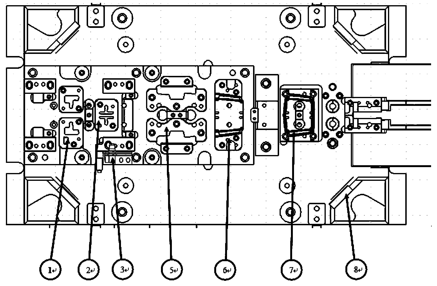
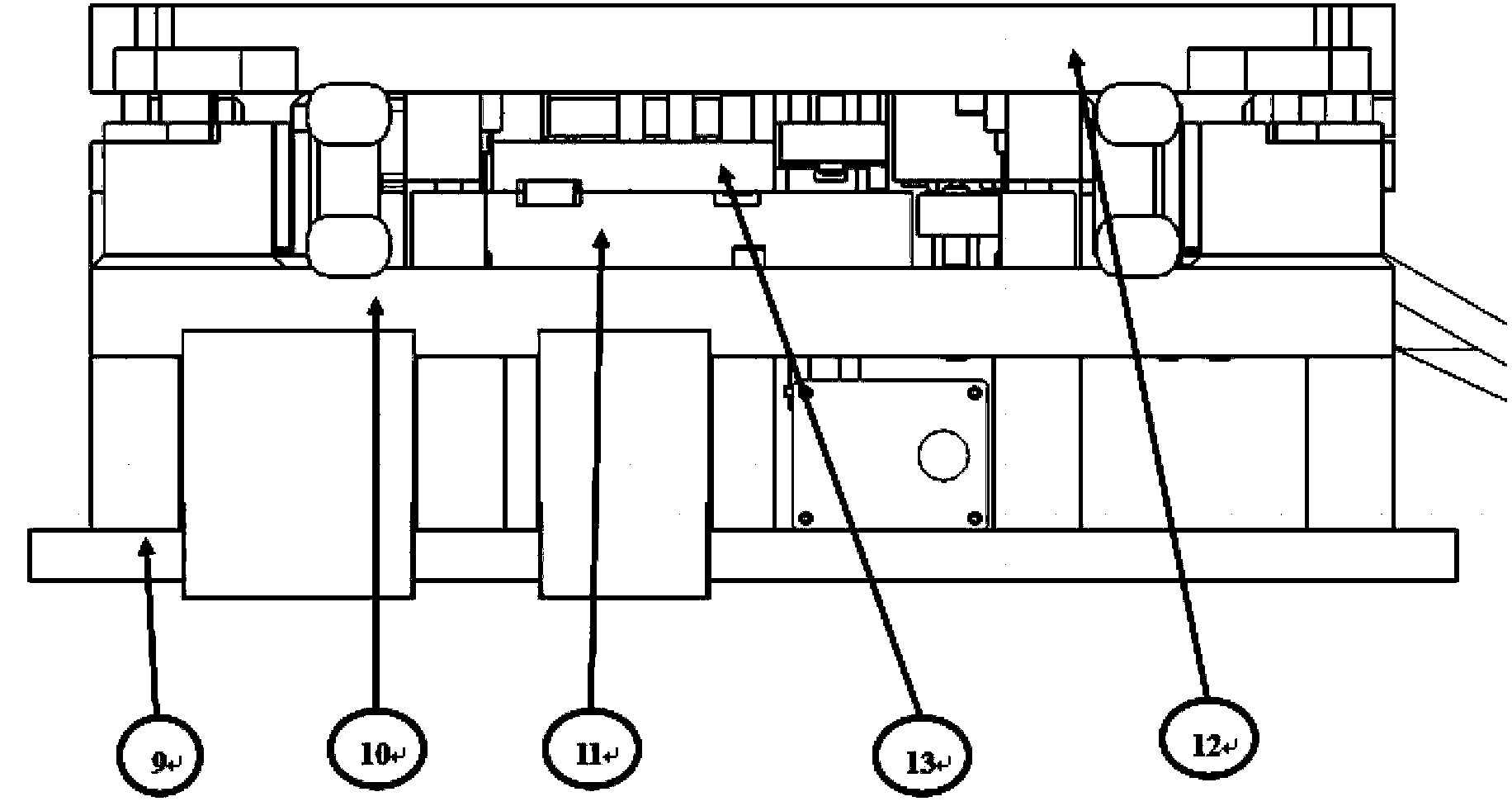
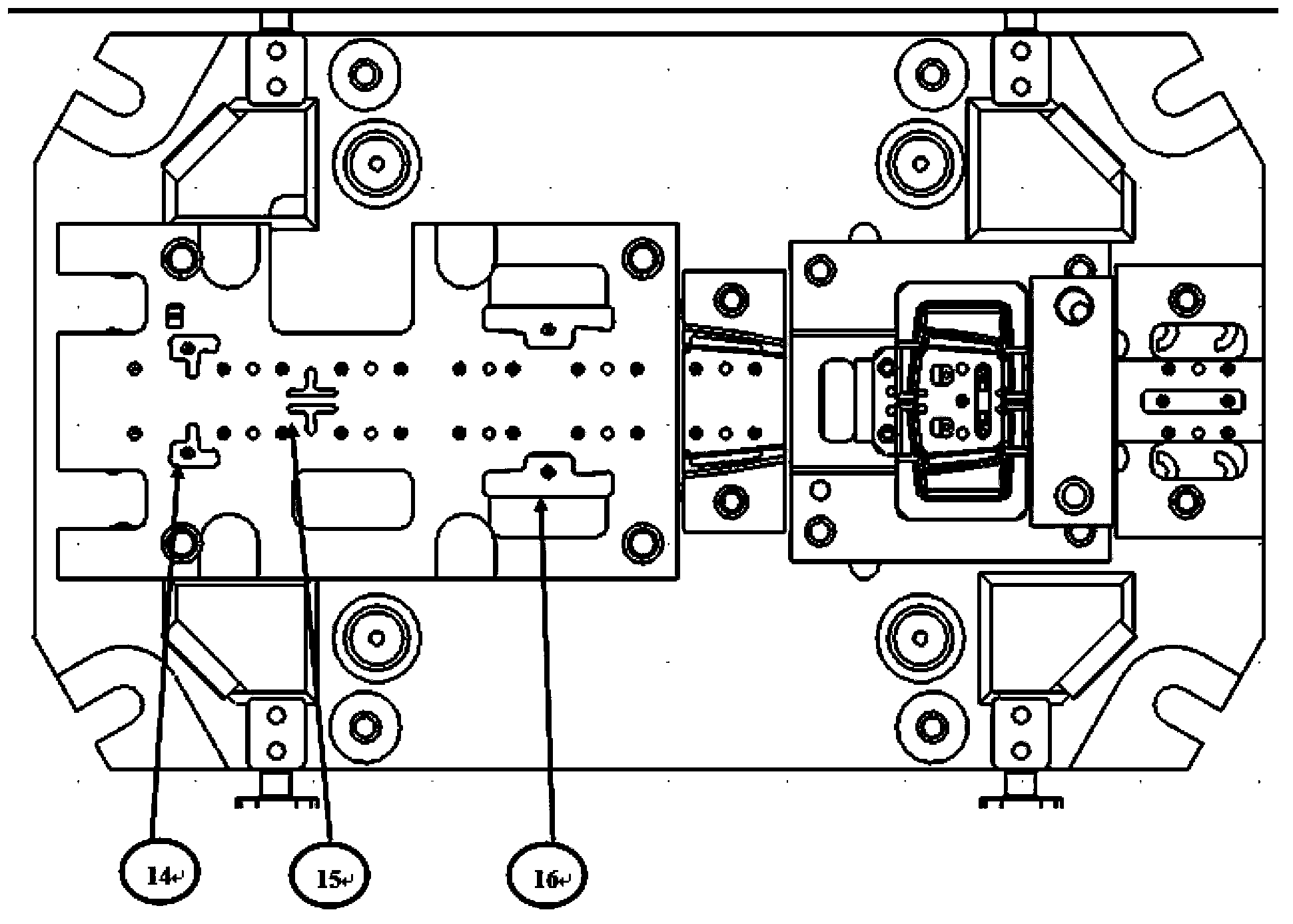
[0024] Such as Figure 1~3 As shown, a progressive mold for a gas spring reinforcement plate is composed of a lower mold part and an upper mold part,

[0025] Described lower mold part comprises die foot 9, lower mold base 10, lower mold punching die 1, lower mold trimming knife block 2, feeding sensor 3, lower mold forming knife, lower mold guide plate 8, ejector plate 11 , the mold foot 9 and the mold foot pad are arranged at the bottom of the mould, the lower mold base 10 is arranged on the upper plane of the mold foot 9, the lower mold punching die 1, the lower mold trimming knife block 2 , the feeding sensor 3, the lower mold forming knife, and the ejector plate 11 are fixed on the upper surface of the lower mold base 10;

[0026] The upper mold part includes an upper mold pressing plate 13, an upper mold punch 14, an upper mold punching and trimming knife 15, an upper mold forming knife block 16 and an upper mold seat 12, and the upper mold pressing plate 13, upper Die...


PUM


Abstract

The invention relates to a gas spring reinforcing plate grading mold which consists of a lower mold part and an upper mold part, wherein the lower mold part comprises a mold foot (9), a lower mold base (10), a lower mold punching female mold (1), a lower mold trimming cutter block (2), a feeding sensor (3), a lower mold forming cutter, a lower mold guide plate (8) and a jacking plate (11), wherein the mold foot (9) and a mold foot pad plate are arranged at the lowermost part of the mold; the lower mold base (10) is arranged on the upper plane of the mold foot (9); the lower mold punching female mold (1), lower mold trimming cutter block (2), the feeding sensor (3), the lower mold forming cutter and the jacking plate (11) are fixed on the upper surface of the lower mold base (10); the upper mold part comprises an upper mold pressing plate (13), an upper mold punching head (14), an upper mold punching trimming cutter (15), an upper mold forming cutter block (16) and an upper mold base (12). Compared with the prior art, the gas spring reinforcing plate grading mold has the advantages of simple structure, convenience in use, convenience in repairing, stable production and the like.

Description

technical field [0001] The invention relates to a mold, in particular to a progressive mold for a gas spring reinforcing plate. Background technique [0002] The front end of the rear axle housing assembly is connected to the transmission shaft through the main reduction assembly, and the rear end is connected to the automobile leaf spring and the frame through the spring plate seat assembly; the size of the weld seam between the spring reinforcement plate and the axle housing body assembly and the spring reinforcement The plate angle directly affects the strength of the welding seam between the spring plate seat assembly and the axle housing body assembly. [0003] At present, in many cases, the traditional gas spring reinforcement plate mold needs multiple stamping strokes and multiple stamping equipment to complete the production process, which increases the stamping cost. And there are potential safety hazards in the operation of personnel, and the quality of stamping p...

Claims


Application Information

Patent Timeline
Patent Type & Authority Applications(China)
IPC IPC(8): B21D37/10
CPCB21D37/10
Inventor 周峰丛培民姚天胤周勇蔡永峰徐丽莉
Owner SHANGHAI ZHONGDA AUTO PARTS
Learn More