
Steel plate coiling device

A technology of steel plate coiling and tapered grooves, which is applied in the field of steel plate coiling devices to achieve the effect of flexible sliding and favorable coiling

Inactive Publication Date: 2015-02-11
KUNSHAN GUOZHI PRECISION MACHINERY
View PDF5 Cites 2 Cited by
  • Summary
  • Abstract
  • Description
  • Claims
  • Application Information

AI Technical Summary

Problems solved by technology

[0003] Aiming at the deficiencies in the above-mentioned prior art, the main purpose of the present invention is to provide a steel plate coiling device, which can flexibly expand and contract the blade and the main shaft of the reel, and be fixed between the tapered block on the blade and the tapered groove on the main shaft. Flexible sliding, less likely to be stuck and immobile, and conducive to coiling of steel plates

Method used


Image

  • Steel plate coiling device
  • Steel plate coiling device

Examples


Embodiment 1

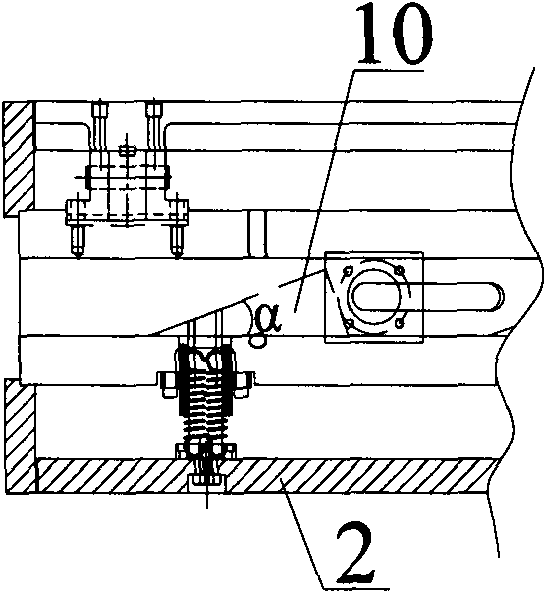
[0015] see figure 1 with figure 2 , Embodiment 1 of the present invention: a steel plate coiling device, including an oil cylinder 4, a telescopic shaft 3, a main shaft 1, and a blade 2, the blade 2 is fan-shaped, and the blade 2 is provided with four pieces, and the four fan-shaped blades 2 are combined into a cylindrical shape structure, the main shaft 1 is placed in the center of the cylindrical structure and extends out of the cylindrical structure, the telescopic shaft 3 is connected to the main shaft 1, and the telescopic shaft 3 is connected to the oil cylinder 4; the main shaft 1 is provided with a plurality of tapered grooves 10, and each blade A tapered bar 20 is provided at the position corresponding to the tapered groove 10 on the 2, and the tapered bar 20 can be embedded in the tapered groove 10 and can move along the slope of the tapered groove 10.

[0016] In this embodiment, the end of the tapered strip 20 in contact with the tapered groove 10 is provided wit...

Embodiment 2

[0019] Embodiment 2: The difference between this embodiment and Embodiment 1 is that in this embodiment, the upper inner wall of the tapered groove 10 and the horizontal plane where the axis of the main shaft 1 is located form an angle α, and the degree of α is 20°; The degree of inclination provided on the end of the tapered strip 20 in contact with the 10 tapered grooves is 20°.

Embodiment 3

[0020] Embodiment 3: The difference between this embodiment and Embodiment 1 is that in this embodiment, the upper inner wall of the tapered groove 10 and the horizontal plane where the axis of the main shaft 1 is located form an angle α, and the degree of α is 30°; The degree of inclination provided on the end of the tapered strip 20 in contact with the tapered groove 10 is 30°.


PUM


Abstract

The invention discloses a steel plate coiling device. The steel plate coiling device comprises an oil cylinder, a telescopic shaft, a main shaft and blades; the blades are in a sector shape; the four sector-shaped blades are combined to form a cylindrical structure; the main shaft is placed in the center of the cylindrical structure and extends out of the cylindrical structure; the telescopic shaft is connected with the main shaft and is connected with the oil cylinder; a plurality of conical grooves are formed in the main shaft; a taper strip is arranged at the position, corresponding to the conical groove, of each blade; the taper strips can be embedded in the conical grooves and can move along the obliquity of the conical grooves. According to the mode, the blades and the main shaft of a coiling block can flexibly expand and retract; taper blocks fixed to the blades flexibly slide in the conical grooves in the main shaft; the dead clamping condition is not prone to happening, and coiling of a steel plate is facilitated.

Description

technical field [0001] The invention relates to the field of steel strip coilers, in particular to a steel plate coiler. Background technique [0002] The coiler is the equipment for collecting and sorting the strip steel products. The quality of its coiling has a direct impact on the final product of the strip steel. As the core component of the coiler, the reel is directly related to the product to be rolled. The reel of the existing coiler is generally composed of four closed blades, and the four closed blades form a cylindrical structure reel. There is a main shaft in the center of the reel, and a plurality of raised taper blocks are arranged on the main shaft. Correspondingly, each blade is provided with a groove that matches the raised taper block, and the reel can be uncoiled or unrolled by matching the raised taper block on the spindle with the groove on each blade Closure, that is, the expansion and contraction of the reel. This structure has the following disadv...

Claims


Application Information

Patent Timeline
Patent Type & Authority Applications(China)
IPC IPC(8): B21C47/30
Inventor 李聪兴
Owner KUNSHAN GUOZHI PRECISION MACHINERY
Learn More