
Ultrafast continuous imaging device and method

The technology of an imaging device and imaging method, which is applied in projection devices, printing devices, optics, etc., can solve the problems of incapable of ultra-fast imaging and low time resolution of imaging means, and achieve the effects of simple structure, low cost and easy realization

Inactive Publication Date: 2015-01-28
BEIJING INSTITUTE OF TECHNOLOGYGY
View PDF5 Cites 12 Cited by
  • Summary
  • Abstract
  • Description
  • Claims
  • Application Information

AI Technical Summary

Problems solved by technology

[0006] The purpose of the present invention is to solve the problem that the time resolution of the existing imaging means is low, it is impossible to perform ultra-fast imaging on the process with an interval of femtosecond to picosecond level, and it is difficult to meet the needs of scientific research and production, and proposes an ultra-fast continuous Imaging device and method

Method used


Image

  • Ultrafast continuous imaging device and method
  • Ultrafast continuous imaging device and method
  • Ultrafast continuous imaging device and method

Examples


Embodiment

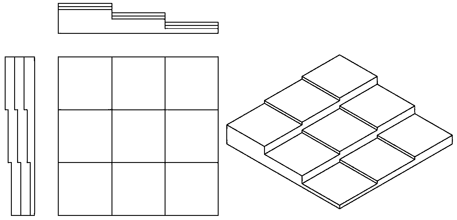
[0029] Such as figure 1 As shown, an ultrafast continuous imaging device includes an ultrafast laser 1, a first beam expander lens 2, a second beam expander lens 3, a time delay device 4, a focusing lens 5, an observation object 6, a discrete lens 7, a camera array8.

[0030] The direction of its optical path is as follows: the ultrafast laser 1 generates an ultrashort pulse beam; after the beam passes through the first beam expander lens 2 and the second beam lens 3, the spot is enlarged and emitted horizontally; the beam covers the entire delayer 4, producing different time delays Sub-pulse: the sub-pulse is focused by the focusing lens 5 and passes through the observation object 6, and the light beam is collimated by the discrete lens 7, and is imaged in the camera array 8.

[0031] An ultrafast continuous imaging method, the implementation steps are as follows:

[0032] 1) First, the ultra-fast laser 1 generates ultra-short laser pulses, and the energy of the pulses is s...


PUM


Abstract

The invention relates to an ultrafast continuous imaging device and method, and belongs to the technical field of ultrafast imaging. The device comprises an ultrafast laser, a first beam expanding lens, a second beam expanding lens, a delayer, a focusing lens, an observation object, a disperse lens and a camera array. According to the method, the ultrafast laser is used for generating femtosecond-order ultrashort pulses, step type lenses with different thicknesses are used for achieving a femtosecond-order delay pulse sequence, different sub-pulses pass the same detecting point through a focusing-dispersing method, and it can be guaranteed that an imaging light beam can be horizontally ejected; imaging is carried out through the camera array at different times. The ultrafast continuous imaging device and method can break through the bottleneck of time resolving power, and the time resolving power is improved to the femtosecond order. For the process with no repeated experiment condition, continuous imaging can be achieved at a time during an experiment. A control circuit is not needed, and cost is reduced. The structure is relatively simple and easy to achieve.

Description

technical field [0001] The invention relates to an ultrafast continuous imaging device and method, belonging to the field of ultrafast imaging. Background technique [0002] In the process of scientific research and technology development, it is often necessary to study some ultrafast processes that occur in a very short time, such as energy transfer, electron excitation, and plasma evolution during femtosecond laser processing. On the order of femtoseconds to picoseconds, the duration of these processes is very short, but the ultrafast changes in this time scale directly affect and determine the quality and accuracy of subsequent processing results. Observing the ultrafast changes in this time scale The process is conducive to revealing the interaction mechanism between femtosecond laser and matter, so there is an urgent need for a continuous imaging device and method with ultrafast time resolution. [0003] Because the traditional high-speed continuous imaging equipment u...

Claims


Application Information

Patent Timeline
IPC IPC(8): G03B29/00
Inventor 姜澜谭旭东胡洁曹强余彦武王安东
Owner BEIJING INSTITUTE OF TECHNOLOGYGY
Learn More