
An axisymmetric lens group structure for thermal effect correction of lithographic projection objective lens

A lithographic projection, axisymmetric technology, used in microlithography exposure equipment, optics, photography, etc., can solve the problems of affecting image quality, complex structure, image quality deterioration, etc., to reduce air gaps, reduce heat resistance, good compensation effect

Active Publication Date: 2017-06-09
BEIJING GUOWANG OPTICAL TECH CO LTD
View PDF5 Cites 0 Cited by
  • Summary
  • Abstract
  • Description
  • Claims
  • Application Information

AI Technical Summary

Problems solved by technology

[0005] The purpose of the present invention is to propose an axisymmetric mirror group structure for correction of the thermal effect of the lithographic projection objective lens, which solves the problems in the prior art that the structure is complex and affects the imaging image quality during the imaging process, and avoids the problem of the lithographic projection objective lens in the working process. The problem of image quality degradation caused by the absorption of laser heat by the material, especially for the problem of asymmetric magnification and constant term astigmatism introduced by the rectangular exposure field of view

Method used


Image

  • An axisymmetric lens group structure for thermal effect correction of lithographic projection objective lens
  • An axisymmetric lens group structure for thermal effect correction of lithographic projection objective lens
  • An axisymmetric lens group structure for thermal effect correction of lithographic projection objective lens

Examples


Embodiment Construction

[0024] Embodiments of the present invention will be further described below in conjunction with the accompanying drawings.

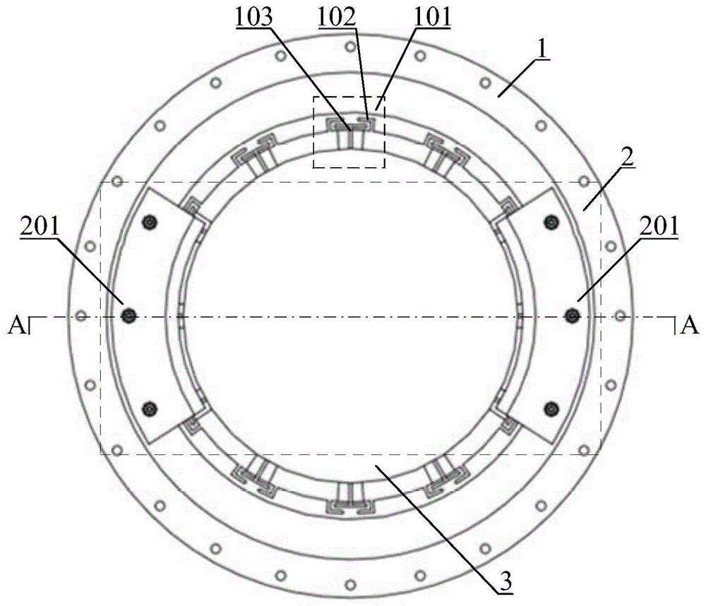
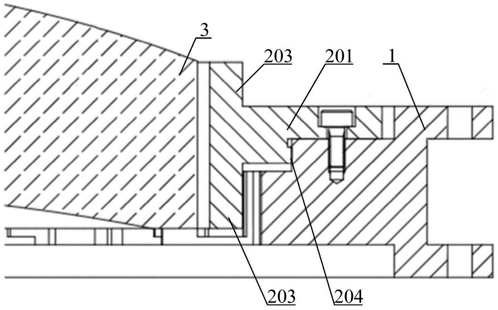
[0025] See attached figure 1 , attached figure 2 And attached image 3 , an axisymmetric lens group structure for correction of thermal effect of a lithography projection objective lens according to the present invention comprises a mirror frame 1, an axisymmetric structure 2 and a lens 3;

[0026] The axisymmetric structure 2 includes two identical fan-shaped areas 201, and the two fan-shaped areas 201 are respectively symmetrical about up and down, left and right; different compensations can be achieved by adjusting the opening angle of the fan-shaped areas 201 of the axisymmetric structure 2 to the center Effect;

[0027] Multiple sets of flexible support units 101 are evenly distributed on the upper circumference of the picture frame 1; the lens 3 is fixedly connected to multiple sets of flexible support units 101 on the picture frame 1 by means ...


PUM


Abstract

The invention relates to a non-axisymmetric lens group structure for lithography projection objective lens thermal effect correction and belongs to the deep ultraviolet lithography projection objective lens image quality compensation filed. The objective of the invention is to solve the problem of image quality deterioration which is caused by a situation in which materials absorb laser heat in the working process of a lithography projection objective lens, and in particular, problems of asymmetric multiplying power and constant term astigmatism which are brought about by a rectangular exposure field of view. The non-axisymmetric lens group structure for lithography projection objective lens thermal effect correction provided by the invention includes a lens frame, a non-axisymmetric structure and a lens; the non-axisymmetric structure consists of two identical fan-shaped areas; the two fan-shaped areas are in longitudinal symmetry and bilateral symmetry respectively; the lens frame is circumferentially and uniformly provided with a plurality of sets of flexible supporting units; the lens is fixedly connected with the plurality of sets of flexible supporting units on the lens frame in a gluing manner; the fan-shaped areas are fixed on the lens frame; gaps are left between the inner side walls of the fan-shaped areas and side wall of the lens; and installation directions of the fan-shaped areas are vertical to the scanning direction of the projection objective lens.

Description

technical field [0001] The invention belongs to the field of image quality compensation for deep ultraviolet lithography projection objects, and in particular relates to an axisymmetric mirror group structure used for correction of thermal effects of lithography projection objects. Background technique [0002] The lithography projection objective lens is one of the three core parts of the lithography machine. In order to meet the development needs of large-scale integrated circuits, the lithography projection objective lens needs to continuously improve its resolution and production efficiency. Improving the resolution of lithography is mainly achieved by shortening the exposure wavelength, reducing the process factor and increasing the numerical aperture of the lithography projection objective lens. At present, the widely used exposure wavelength in commercial production is 193nm, and the numerical aperture of the lithography projection objective lens has reached 1.35. As...

Claims


Application Information

Patent Timeline
Patent Type & Authority Patents(China)
IPC IPC(8): G02B7/02G03F7/20
CPCG03F7/70275
Inventor 于新峰倪明阳李显凌张巍隋永新杨怀江
Owner BEIJING GUOWANG OPTICAL TECH CO LTD
Learn More